Continue to Site

Welcome to EDAboard.com

Welcome to our site! EDAboard.com is an international Electronics Discussion Forum focused on EDA software, circuits, schematics, books, theory, papers, asic, pld, 8051, DSP, Network, RF, Analog Design, PCB, Service Manuals... and a whole lot more! To participate you need to register. Registration is free. Click here to register now.

Transformer" LESS" invertor

Status
Not open for further replies.

amjadali56

Full Member level 3
Joined
Sep 17, 2007
Messages
151
Helped
39
Reputation
78
Reaction score
36
Trophy points
1,328
Location
Earth
Activity points
2,041
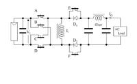
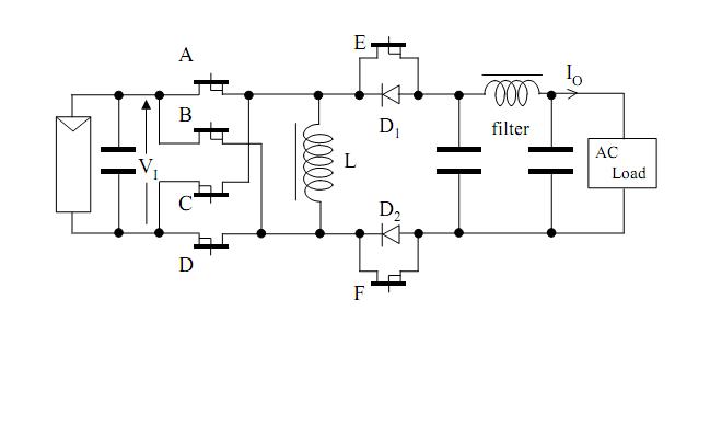
I propose the new type transformer less inverter whose basic topology should be buck boost converter. The greatest characteristic of this inverter would be that it will has only one stage to generate AC power. It means that simple circuitry can be realized. The control method for the proposed inverter
using the particular characteristic of buck boost converter. To control duty ratio of the main switches, the wide range voltage matching is feasible.


looking for useful help comments and citation.:)
 

Hi,
While it may be achievable, think of the required duty cycle and the amount of peak current at that duty cycle. I don't think it's feasible, if this is for an inverter that converts from 12/24/48vdc input and 220v output.

Hope this helps.
Tahmid.
 

can u be more specific about the components u are using i am interested to make this design as my project .....
 

can u be more specific about the components u are using i am interested to make this design as my project .....
MOSFETs, capacitors, inductors. I don't expect, that the original poster has yet considered a more specific componen choice. Why don't you evaluate the circuit properties on your own?
I don't think it's feasible, if this is for an inverter that converts from 12/24/48vdc input and 220v output.
Feasible though, but reasonable?

The circuit's low part count looks interesting at first sight. But I agree with Tahmid, that some properties are questionable.

- With low input voltage, the low duty cycle, and high primary peak voltage respectively secondary peak current has been mentioned. As a result the switched power is a multiple of the converter throughput, resulting in increased switching losses compared to a transformer inverter. The circuit may perform better when operated as a high input voltage solar string converter.

- As the circuit is basically operating as inverted buck-boost, all energy has to go through the inductor, requiring a larger core than a push-pull transformer converter.

- The pulsating energy flow of the single phase converter (between 0 and 2*Pavg) has to be buffered by the input capacitor, the primary switch must have a rating of 2*Pavg. A two-stage converter can buffer energy in the bus capacitor.

I wonder, if amjadali56 has designed the circuit on his own or copied it from a scientific paper?
 

Status
Not open for further replies.

Part and Inventory Search

Welcome to EDABoard.com

Sponsor

Back
Top