Continue to Site

Welcome to EDAboard.com

Welcome to our site! EDAboard.com is an international Electronics Discussion Forum focused on EDA software, circuits, schematics, books, theory, papers, asic, pld, 8051, DSP, Network, RF, Analog Design, PCB, Service Manuals... and a whole lot more! To participate you need to register. Registration is free. Click here to register now.

transformer for 555 taser gun

Status
Not open for further replies.

redpepper007

Newbie level 4
Joined
Apr 19, 2012
Messages
6
Helped
0
Reputation
0
Reaction score
0
Trophy points
1,281
Activity points
1,325
So, basically i'm going to create a 555 based taser with somewhere about 20-30kV output (input is 9V or 3*18650 in series). Found this schematic on google and it seems kinda simple:

4sh3xs7xzq2gnllxl5uq.gif


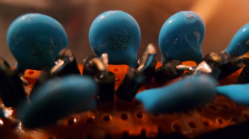
so I went to nearby electronics store and got all components except for the transformer. They had no idea what does 1k:8R means and asked me for input/output voltages - does anyone knows what kind of transformer would be okay? And if that matters, I'm gonna add a few more voltage multiplier stages (total of 5 or 6)
 

Erm... OK... first off, the Taser (Thomas A. Swift electric rifle - yes, really) is a different thing to a simple 'stun gun'. Tasers use controlled pulse rate and energy transfer unlike a stun gun which, at best, tries to use a certain frequency at which the human nervous system is easily effected. Generally, they don't even do that.

See: **broken link removed** for a little information. There is more out there if you dig.

I've not seen a commercial stun gun design that uses a Cockcroft-Walton multiplier ladder after the transformer. Usually the transformer is wired directly to the electrodes.

Neither designs are safe things to play with; there's a fine line between scrambling the nervous system and causing, for instance, ventricular fibrillation. But, I'm not the safety police, otherwise I wouldn't do half the things I do.

As to the transformer: I have seen ready-made stun gun coils for sale on a US web site. I can't remember which one now, but they sold lots of 'interesting' (read dubious) electronic kits and projects.

The difficulty is making one that can handle the high voltage. Inter-winding layers of high voltage tape help, as does impregnating the coil in transformer varnish. An old TV flyback transformer makes a suitable (if awkwardly shaped) transformer for a small stun gun, by the way.

There's alot of information out there, if you search deeply. Some of it is even useful.
 
I udnerstand that high voltages with low currents is not a toy and I am not going to stun everyone just for fun. If this works out, I'll use it for self defense purposes as I tend to visit places I shouldnt normally walk in (like abandoned buildings with homeless dudes and their crazy dogs, drug addicts etc).

One more thing - what kind of isolation do I need for the soldering? I'm gonna plant this on a standart PCB board and those holes for soldering are really close to each other, and as we are dealing with very high voltages, there migh be electric sparks, right?
 

Dealing with high voltages is tricky. Using fibreglass PCB laminate, there are tables giving 10mm per kilovolt for track spacing. You could probably get away with as little as 5mm per kV since it's not a 'critical' circuit. Any grease (just from fingerprints) on the PCB will cause leakage, and any sharp points will cause corona loss. Soldering must be done by cutting the leads just long enough to solder, then soldering to a smooth 'ball' of solder around them. Then the whole thing needs coating with HV varnish or HV conformal coating.

The circuit you have found is not good. If it actually gave 20kV as the designer thinks it will, then the capacitors and diodes are underrated by an order of magnitude. The transformer would need to be giving 5kV peak (there are 4 stages to get to 20kV) - the 1n4007 diodes and 400V capacitors will die, quickly, as the thousands of volts arcs through them. Components for such voltages are not small(!) which is probably one reason why commercial circuits just have the output from the coil.

Sorry to be the bearer of bad news, but things aren't as simple as the designer thinks.

I've built quite a few high voltage things, from powerful whole-building ionizers to 'special effects' things like that arc that travels up two angled wires - I forget what it's called. I've never tried to make a stun gun (although I studies the circuits some years ago) but the high voltage principles are no different.
 
Well, then it would be enough if I soldered all components on the PCB and then isolated the whole thing in a 3mm plastic case, leaving just the two electrodes out? Or do I need to isolate the components from each other on the PCB too, when dealing with HV?

As for the bad news, then I guess this will be yet another small DIY project. Buying a real stun gun / taser should be more reliable choice for self defense :D
 

Here is a lower-voltage ladder multiplier (built a long time ago, for a peaceful purpose!), you can see they are 2kV capacitors (4.7nF) and 1N4007 I think..
At this kind of spacing, expect it to arc unless you coat it in plastic (some product called "conformal coating" as far as I can
remember). It is a transparent coating, so hard to see, but the components and board are heavily coated in it.
Bear in mind that even a small (few nF) capacitor rated at 15kV or more will be about 15-20mm diameter and
1cm thick..
 
what about hot glue - is it a good isolator for these kinds of voltages?
 

possibly, but I don't think anyone has tested hot-glue for HV isolation, so it might be ok, or it might not be. With Varnish as mentioned by FoxyRick, or conformal coatings, they have been proven, to tens of kV as far as I'm aware. Transformers use varnish (or older ones use shellac which is a natural type of varnish)..
 
If you are not going to try to make that circuit into a stun gun (while I understand your reason probably more than most would, I really don't recommend it - I would not want to risk my life on it - it's far more likely just to annoy someone than hurt them, and get you killed when you could have escaped otherwise.) then there is lots of fun to be had with HV. Ionizers, ion-powered turbines and tiny moving models, moving arcs (I remember now - called 'Jacob's ladder'), arc cutters...

For safety though - add a chain of resistors to the output electrode to limit current to a mA or less. That way an accidental touch won't stop your heart!

I don't know about hot glue for HV - never tried it. Follow my points about minimum separation of everything from the coil's output onwards.

You could use perfboard (as Sky_123 has) but fibreglass PCB would be better. It would be easy to make, even using rub-on transfers (like us oldies used to use) due to the large spacing and wide tracks.

When soldering, the idea is to make sure that no component lead ends show through the solder. These have sharp edges when cut and will cause corona loss: charge concentrates at a sharp points, causing electrons to jump on or off depending on polarity - this is how an ioniser works. So do 'poor' soldering, making sure to have a nice, round, shiny 'blob' of solder covering the ends. That's also why you must cut the lead before soldering, of course. Avoid sharp bends in the leads themselves, for the same (if not as critical - it's not as sharp) reason.

The component leads and tracks will need insulating - air is not a good insulator at high voltages. Everything on the HV side will need coating.

If you are lucky enough to get a transformer that actually does give out five thousand volts, or use a flyback transformer, then I still say that the multiplier will die almost immediately. Old TV repair shops are good sources of flyback transformers, high voltage diodes and capacitors - I used to salvage mine from the local tip! More likely though any other transformer might give you a lot less voltage and the circuit might survive and produce a few thousand volts output. I ran my multipliers straight from 230Vac mains, so 'normal' diodes and mains-rated capacitors could be used. It takes a lot of them to get up to 10kV though.

Playing with a flyback transformer is an easy and fun way to make 10kV or more. That's how I started. Flyback transformers from TV's and monitors from about 15-20 years ago or younger are usually better than older ones. They already incorporate a diode and give around 25kV. Earlier ones are simpler (and still useful to play with) but have external multiplier components (useful parts) and only give about 8kV from the transformer itself.

One more thing to be cautious of: Ozone. It's good stuff up in the atmosphere, but very bad stuff down here. I forget the lethal concentration in air but it isn't much! Are you familiar with the 'electrical' smell behind old, tube television sets or old photocopiers and laser printers? That's a tiny amount of ozone from corona loss in the HV circuits. Pleasant in such tiny amounts, but people have been made very ill by working in small rooms with a photocopier before it was recognized as dangerous and the construction (and ventilation in rooms) improved.

My 25kV flyback generator, allowed to arc, produced so much that it made me feel really nauseous and dizzy with a minute or so of running it. I didn't know why - that's when I found out about ozone and how deadly it is. Be careful in there!

Here are some links to HV circuits:

http://www.powerlabs.org/flybackdriver.htm
**broken link removed**

Edit to add: I forgot to reiterate cleanliness when making the board. Make sure to clean off all traces of flux and grease (use a mild solvent or proper flux cleaner) before coating the board. Otherwise the HV will just leak through the flux and grease under the coating.
 
Last edited:
So, basically, you would suggest me not to create this circuit? Because if I am risking my own life in case something goes wrong, i'll better use the components I bought for something else :D
 

There are lots of other fun apps for HV. As FoxyRick says, it's unlikely the transformer will supply 5kV, so you could assemble the circuit and experiment (do it safely! : ) with the HV for academic purposes. I used mine to power some image tube at one time.
It's safe (i.e. to you) even if it arcs, as long as you're not within (say) a feet of it. However, if you follow the advice on construction and coating the parts, then it won't arc either. The ozone smell you'll soon get to recognise.. it's a very
unusual smell if you've not smelt it before, and if you open a window you'll be fine.
 

Yes, I know what's ozone and I love that smell actually... :D used to mess around with some high voltage arc generator back in the highschool
 

Status
Not open for further replies.

Part and Inventory Search

Welcome to EDABoard.com

Sponsor

Back
Top