Continue to Site

Welcome to EDAboard.com

Welcome to our site! EDAboard.com is an international Electronics Discussion Forum focused on EDA software, circuits, schematics, books, theory, papers, asic, pld, 8051, DSP, Network, RF, Analog Design, PCB, Service Manuals... and a whole lot more! To participate you need to register. Registration is free. Click here to register now.

trans impedance amplifer

Status
Not open for further replies.

nisha gupta

Member level 4
Joined
May 22, 2012
Messages
71
Helped
0
Reputation
0
Reaction score
0
Trophy points
1,286
Location
Hyderabad, Andhra Pradesh, India
Activity points
1,755
hi
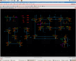
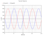
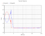
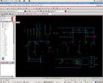
i have designed a transimpedance amplifier having UGB 1GHZ and gain 60dB in AC analysis. but in transient analysis it is giving at output sin wave only upto 1.5MHz. after that frequency some sandom signal is coming why so?
 

Beyond about 1MHz your TIA's gain falls with at least -20dB/decade, so its output cannot follow its input any more, perhaps this is what you describe as random signal?

In order to get more help you'd better provide more info on your circuit (schematic), test bench (schematic), and sim. results (curves).
 

Also in the transient (large-signal) analysis the effects of amplifier slew-rate limitations come into play, which aren't shown in the AC (small-signal) analysis.
 

i am attaching schematic and transient plot at 1.5M and 2M. now plz tell me what could be the problem
 

Attachments

  • OPAMP.png
    OPAMP.png
    91 KB · Views: 73
  • trans.png
    trans.png
    9.4 KB · Views: 56
  • trans1.png
    trans1.png
    5.6 KB · Views: 64

What's the difference in the simulation parameters between the good plot and the bad plot?
 
Last edited:

What's the difference in the simulation parameters between the good plot and the bad plot?
Apparently a slightly increased slew-rate.

The circuit is a way more than a simple transimpedance amplifier, it's a fully differential amplifier with common mode feedback circuit. It looks like the circuit runs into a common mode latch-up, either due to an inappropriately designed CMFB circuit or simply a wrong test setup.

The good thing with a simulation is that you can inspect every circuit node, so you can figure out why the latch-up occurs.
 

It's not a Transimpedance Amplifier... It looks like simple Differential Pair follwoing Output Stage..

The Input of a Transimpedance Amplifier is always Current,not voltage.So, using a differential pair with CMOS transistors at the input stage is not correct..
 

It may be because of common mode problem. You can check your circuit for proper input Common mode range and Output common mode range to make sure saturation region for all MOSes.

Try to give small amplitude signals.. since your gain is high. And for a differential amplifier -3dB bandwidth is important.

So consider this and UGB is different.

thanks
 

It's not a Transimpedance Amplifier... It looks like simple Differential Pair follwoing Output Stage..

The Input of a Transimpedance Amplifier is always Current, not voltage. So, using a differential pair with CMOS transistors at the input stage is not correct..

He didn't show it in the current thread, but in , which shows differential 10nA ac input currents (top left), and symmetrical differential RC feedBack with R≈3kΩ, C value not recognizable (bottom right).

If the configuration is still the same, I think together with the test setup it could be called a TIA.

I don't think so..

Outputs have been connected crossly to the inputs by paralle R-C circuits.So where the input current will flow to ??
He used a Common Mode Feedback to compansate Output Off-Set that aligns the bias circuits but I can still not seee any "Input Current"...
There must be an Input Current to able to say "Transimpedance" that converts current to voltage...
 

hi everyone
thanks for helping
i have design TIA successfully. it is working fine 3dB BW is 15MHz. i have given isin at input. but if i m putting one more ac source voltage or current with frequency it is not working. and this ac source is not connected to TIA anywhere. why this problem is coming. plz tell me.
 

... i have given isin at input. but if i m putting one more ac source voltage or current with frequency it is not working. and this ac source is not connected to TIA anywhere. why this problem is coming.

Nisha, you should show the schematic of your test bench, in which your circuit setUp isn't working. Or do you think we can guess it?
 

Nisha, you should show the schematic of your test bench, in which your circuit setUp isn't working. Or do you think we can guess it?

hi erikl
i already posted schematic in above circuit now again i posting. plz let me know the problem
 

Attachments

  • OPAMP.png
    OPAMP.png
    127.3 KB · Views: 56

hi erikl
i already posted schematic in above circuit now again i posting. plz let me know the problem

Hi nisha,
the schematic which you posted in your above thread (OPAMP.png (91.0 KB)) did not contain your test bench setUp, which is important to evaluate your problem.

Now your new OPAMP.png (127.3 KB) does. Let's see what people find out!
 

Status
Not open for further replies.

Part and Inventory Search

Welcome to EDABoard.com

Sponsor

Back
Top