Continue to Site

Welcome to EDAboard.com

Welcome to our site! EDAboard.com is an international Electronics Discussion Forum focused on EDA software, circuits, schematics, books, theory, papers, asic, pld, 8051, DSP, Network, RF, Analog Design, PCB, Service Manuals... and a whole lot more! To participate you need to register. Registration is free. Click here to register now.

Traffic light controller has no output

Status
Not open for further replies.

alikaradag

Newbie level 6
Joined
Nov 9, 2014
Messages
11
Helped
1
Reputation
2
Reaction score
0
Trophy points
1
Activity points
122
Hi all ,
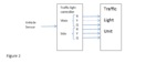
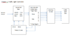
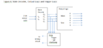
Pleas, I need help with my code. I need to generate 25 seconds (green red signal ) and 4 seconds (yellow signal ). There should be a car sensor too. The code should be based on 24 MHz frequency.
Am not good about vhdl, BUT I really really did my best to write the code bellow. The problem is I couldn't get the four states outputs. I only get the first Green Red state while the other three states are not there!!
Please, any advice or assistance.
code is :


Code VHDL - [expand]
1
2
3
4
5
6
7
8
9
10
11
12
13
14
15
16
17
18
19
20
21
22
23
24
25
26
27
28
29
30
31
32
33
34
35
36
37
38
39
40
41
42
43
44
45
46
47
48
49
50
51
52
53
54
55
56
57
58
59
60
61
62
63
64
65
66
67
68
69
70
71
72
73
74
75
76
77
78
79
80
81
82
83
84
85
86
87
88
89
90
91
92
93
94
95
96
97
98
99
100
101
102
103
104
105
106
107
108
109
110
111
112
113
114
115
116
117
118
119
120
121
122
123
124
library ieee;
use ieee.std_logic_1164.all;
 
ENTITY traffic_traffic IS
PORT(
    CLK: in std_logic;
    LIGHTS: buffer std_LOGIC_VECTOR(5 downto 0));
END traffic_traffic;
 
ARCHITECTURE circuit OF traffic_traffic IS
    TYPE STATE_TYPE IS (S0, S1, S2, S3);
    SIGNAL state: STATE_TYPE := s0;
     signal GrayCode : std_LOGIC_VECTOR (1 downto 0);
     SIGNAL state_outputs : std_LOGIC_VECTOR (3 downto 0);
     SIGNAL trigger_long : std_LOGIC_VECTOR (1 downto 0);
     SIGNAL trigger_short : std_LOGIC_VECTOR (1 downto 0);
 
BEGIN
     PROCESS (GrayCode)
       BEGIN
            CASE GrayCode IS
                WHEN "00" => state <= s0;
                WHEN "01" => state <= s1;
                WHEN "11" => state <= s2;
                WHEN "10" => state <= s3;
                WHEN others => state <= s0;
                     END CASE;
                     end process;
       process (state)
                begin
                CASE state IS
                WHEN s0 => state_outputs   <= "0001";
                WHEN s1 => state_outputs   <= "0010";
                WHEN s2 => state_outputs   <= "1000";
                WHEN s3 => state_outputs   <= "0100";
                WHEN others => state_outputs <= "0001";
                     END CASE;
END PROCESS;
   process (state_outputs)
                begin
                CASE state_outputs IS
                WHEN "0001" => lights <= "100001";
                WHEN "0010" => lights <= "010001";
                WHEN "1000" => lights <= "001100";
                WHEN "0100" => lights <= "001010";
                WHEN others => lights <= "100001";
             END CASE;
END PROCESS;
   process (lights)
                begin
                CASE lights IS
                WHEN "100001" => trigger_long <= "10";
                WHEN "010001" => trigger_short <= "01";
                WHEN "001100" => trigger_long <= "10";
                WHEN "001010" => trigger_short <= "01";
                WHEN others => trigger_long <= "10";
             END CASE;
END PROCESS;
 
END ;
 
library ieee;
use ieee.std_logic_1164.all;
use ieee.std_logic_arith.all;
 
-- the Timer for the traffic light controller.
 
entity timer is
PORT(clk: in std_logic;
     reset: in bit;
    LIGHTS: out std_LOGIC_VECTOR(5 downto 0));
END timer;
architecture arc of timer is
    TYPE STATE_TYPE IS (S0, S1, S2, S3);
    SIGNAL state: STATE_TYPE := s0;
    signal count: integer := 24000000;
    signal trigger_long: integer  := 600000;
    signal trigger_short: integer  := 96000;
     signal car_detec: integer range 0 to 1;
BEGIN
PROCESS (CLK,reset, state, trigger_short, trigger_long, car_detec)
BEGIN
    IF (reset = '0') THEN
      IF(CLK'EVENT AND CLK = '1') and car_detec = 1 THEN
        CASE state IS
            WHEN s0 =>
                IF count < 24000000 / 40 THEN
                    state <= s0;
                    count <= count + 1;
                ELSE
                    state <= s1;
                    count <=  0;
                END IF;
            WHEN s1 =>
                IF count < 24000000 / 250 THEN
                    state <= s1;
                    count <= count +1;
                ELSE
                    state <= s2;
                    count <= 0;
                END IF;
            WHEN s2 =>
                IF count < 24000000 / 40 THEN
                    state <= s2;
                    count <= count + 1;
                ELSE
                    state <= s3;
                    count <= 0;
                END IF;
            WHEN s3 =>
                IF count < 24000000 / 250 THEN
                    state <= s3;
                    count <= count + 1;
                ELSE
                    state <= s3;
                    count <= 0;
                END IF;
            WHEN others =>
                    state <= s0;
    END CASE;
    END IF;
    END IF;
    END PROCESS;
     end arc;

 
Last edited by a moderator:

First glaringly obvious problem are these lines:
Code:
IF (reset = '0') THEN
  IF(CLK'EVENT AND CLK = '1') and car_detec = 1 THEN
This isn't a synthesis template for an inferred register in VHDL. The synthesis template looks like this:
Code:
-- asynchronous reset rising edge triggered flip-flop
dff: PROCESS (CLK, RESET)
BEGIN
  IF RESET = 0' THEN
    -- reset code
  ELSIF rising_edge (CLK) THEN
    -- code that is scheduled on each rising edge of the clock
  END IF;
END PROCESS;

The car_detec should not be in the clock portion of the if. Also the reset never does anything when it's '1' (assuming you want an active high reset).

Style wise you shouldn't mix upper and lower case for the same name of a signal clk/CLK etc. Sure VHDL allows this as it's case insensitive...(like you can speed on a mountain road)...but you probably don't want to do this.

There also doesn't seem to be any relationship between the traffic_traffic and timer code, is there supposed to be more code?

You do understand that VHDL is a hardware description language? Do you have a block diagram and a state diagram of the circuit?

- - - Updated - - -

traffic_traffic has this line in the port declaration:
LIGHTS: buffer std_LOGIC_VECTOR(5 downto 0)
but it's never assigned but gets used here:
process (lights)

There are quite a few more problems with the traffic_traffic code, far too many to go through.

I think you need to go through a VHDL tutorial before continuing.
 

Thank you so much ads-ee for your hints and advice......... really now am so depressed ... I know am not good about vhdl but this is my first semester in this field .........

- - - Updated - - -

Traffic Signal Project
General System Requirements
A digital controller is required to control a traffic signal at an intersection of a busy main street and less travelled side street. The green light on the main street is for a minimum of 25 s or as long as there is no vehicle on the side street. The green signal for the side street stays green as long as there is a car on the side street or for a maximum of 25 s. There is a yellow caution light for 4 s between all changes from green to red. Refer to figure 1.
State 0 - MG, SR State 1 - MY, SR State 2 - MR, SG State 3 - MR, SY


State 0: 25 seconds minimum or as long as there is no vehicle on side street.
State 1: 4 seconds
State 2: 25 maximum or until there is no vehicle on side street.
State 3: 4 seconds

The system must control 6 pairs of signals – red, yellow, green light on each side of the main street and also each side of the side street. There is also a sensor input to indicate if there is a vehicle on the side street. See figure 2.

Using the minimal system block diagram, you can begin to fill in the details. The system has four states, as shown in figure 1. So a sequential circuit is needed to control the sequence of states. Also, circuits are needed to generate the proper timing intervals of 25 s and 4 s, as well as a clock signal for the sequential logic.
The time intervals (long and short) as well as the vehicle sensor output are inputs to the sequential logic to determine the sequence of states.

Logic circuits are also required to determine which of the four states the system is in at any given time, to generate the proper output to the lights (state decoder and output logic), and to initiate the long and short time intervals.
Finally, an interface circuit is needed to convert the output logic levels of the state decoder and output logic to the voltages and current required to turn on each of the lights. See figure 3.

our focus is on the state decoder, output logic and trigger logic block for now. See figure 4.
Draw the state diagram based on figure 1. You must first define the variables that determine how the system sequences through its states. The variables and the symbols for this project are as follows:
• Vehicle present on side street = V
• 25s timer is on = TL
• 4s timer is on = TS

Set up the state table that lists the State inputs versus the light outputs and the trigger outputs (long and short).

STATE INPUTS STATE
OUTPUTS LIGHT OUTPUTS
TRIGGER OUTPUTS
S1 S0 O3 O2 O1 O0 MG MY MR SG SY SR Long Short
0 0 0 0 0 1 1 0 0 0 0 1 1 0
0 1 0 0 1 0 0 1 0 0 0 1 0 1
1 1 1 0 0 0 0 0 1 1 0 0 1 0
1 0 0 1 0 0 0 0 1 0 1 0 0 1

Figure 4. State Decoder, Output Logic and Trigger Logic
 

Attachments

  • fig 1.PNG
    fig 1.PNG
    19.9 KB · Views: 91
  • fig 2.PNG
    fig 2.PNG
    9.8 KB · Views: 87
  • fig 3.PNG
    fig 3.PNG
    20.5 KB · Views: 90
  • fig 4.PNG
    fig 4.PNG
    16.9 KB · Views: 84

Thank you so much ads-ee for your hints and advice......... really now am so depressed ... I know am not good about vhdl but this is my first semester in this field .........

Traffic Signal Project
General System Requirements
A digital controller is required to control a traffic signal at an intersection of a busy main street and less travelled side street. The green light on the main street is for a minimum ......
Uh, does this mean you want someone else to design this for you?

You need to step back and draw (not code), let me repeat that, DRAW a detailed block diagram of the internals of each of the blocks your professor gave you as a starting point for the design. Those drawings will show all the flip-flops and logic you will need to implement that block of code. Then you translate that detailed block diagram into VHDL. The state machine for controlling this is pretty much the same idea regardless of the language: VHDL, Verilog, C, python, basic, etc. Pretty much all FSMs are the same regardless of language, syntax may differ but the concept of states and transitions are identical. The main difference with VHDL/Verilog and software languages is how you handle the perception of time, i.e. how long you stay in a state before the next state transition. In HDLs you need a clock and flip-flops to update the state variable and that clock defines the length of time you stay in a state before the next state transition. The clock is the FSMs timebase. If you need to stay in a state for a specific duration then you will need a counter that will count up to that time delay and then transition to the next state based on the terminal count value and input signals to the FSM.

Hopefully I haven't confused you even more. :thinker:
 
hehehehe your comments and advice did the opposite ads-ee and am not confused anymore................. actually I did more and more work and I did the right work finally.... I got some hints from my professor too ..... and just right now I finished the code and got the correct waveform ( as I would assume and see )............... thanks for your support.
 

    V

    Points: 2
    Helpful Answer Positive Rating
hehehehe your comments and advice did the opposite ads-ee and am not confused anymore................. actually I did more and more work and I did the right work finally.... I got some hints from my professor too ..... and just right now I finished the code and got the correct waveform ( as I would assume and see )............... thanks for your support.

Hello Alikaradag,
Please can you help and me with that code?i have the same project from my professor,the same time the same diagram,i have created state decoder schematic,light output logic,trigger logic,timer circuit and sequencial circuit,but i am not good with vhdl,please you are really thankfull if you send to me :)
 

Status
Not open for further replies.

Part and Inventory Search

Welcome to EDABoard.com

Sponsor

Back
Top