Continue to Site

Welcome to EDAboard.com

Welcome to our site! EDAboard.com is an international Electronics Discussion Forum focused on EDA software, circuits, schematics, books, theory, papers, asic, pld, 8051, DSP, Network, RF, Analog Design, PCB, Service Manuals... and a whole lot more! To participate you need to register. Registration is free. Click here to register now.

[SOLVED] To convert 6v into 5v using Zener and resistor combination circuit

Status
Not open for further replies.

speedEC

Full Member level 6
Joined
Apr 1, 2011
Messages
337
Helped
23
Reputation
46
Reaction score
21
Trophy points
1,298
Activity points
4,324
Dear All,

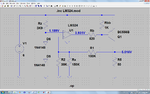
I have 6.2v, 4.2Ah sealed alkaline battery. I have to supply 5v to PIC MCU (PIC16F628A) and Wireless Receiver Module(ST-RX02-ASK Wireless Module). I have decided to use Zener (5.1v) with resistor combination circuit to accomplish the task. Now, I have to select the resistor value. Can any one pl help me to select the correct resistor value?

I went thro' some documents on web related to this circuit but little confusing on how to select the correct resistor value.

NOTE: Wireless module requires 5v and 3mA maximum. pl see the attached PDF file.

View attachment ST-RX02-ASK.pdf

thanks
pmk
 

Another option is just to use two normal diodes (1N400X) connected in series to lower the voltage from the battery ..
Each diode drops roughly 0.65V and I don't think the "5V" for PIC and wireless module is so critical ..

:wink:
IanP
 
From datasheet, the test current for 5.1v zener is 49mA. Even if the battery is low, say 5.5v, the current should be 49 or 50mA. So, to select the resistor value at the minimum battery voltage (in order to work correctly the 5.1v zener):

[ [5.5v (Supply) - 5.1v (Zener) ] / 0.05] = [0.4 / 0.05] = 8 ohms. Is this correct?

If so, the maximum current that can flow into 5.1v zener is 178mA.

But, if the 6v battery is fully charged and at 6.9v, then

[ [6.9v (Supply) - 5.1v (Zener) ] / 8 (R)] = [1.8v / 8] = 0.225 Amps or 225 mA. This crosses the maximum limit. Did I made anything wrong in the calculation?

zener-datasheet-1.jpg

thanks
pmk
 
  • Like
Reactions: DrWhoF

    DrWhoF

    Points: 2
    Helpful Answer Positive Rating
Using a zener regulator is a basically a bad idea for a battery powered design, because it requires a battery current larger than the maximum circuit supply current to achieve regulation. The suggested series diodes are always an option, for a more exact regulation a low quiscent current + low dropout linear voltage regulator should be considered.

I presume, the question is about a real design problem, not an arbitrarily constructed zener diode exercise.

P.S.: To fully utilize the battery capacity, you have a deal with battery voltages down to e.g. 4.4 V. A LDO regulator would supply the battery voltage minus a small (e.g. 50 to 100 mV) voltage drop, if you select a suitable type. If a better regulation for low battery situation is required, you have to go for a buck/boost switching mode regulator.

P.P.S.: E.g. National LP2985
 
Last edited:
Thanks IanP. What happen, if the battery voltage goes low to 5.5v? 5.5v - 1.4 (2 diodes drop x 0.7v) = 4.1v. Yes. PIC MCU can run on this voltage. But, I don't know wireless receiver works. The datasheet of wireless receiver states that the supply voltage is +5v. Also, voltage is also fluctuating? Am I right? If the battery voltage voltage decreases, the voltage on Diode output also decreases? Will this affect the PIC or Receiver?

Thanks
pmk

---------- Post added at 16:25 ---------- Previous post was at 16:22 ----------

Thanks FvM,
Can you refer any Low voltage Drop out Regulator?

thanks
pmk
 

Use a series resistor 6.2K with zener MMBZ5231BL, G
6.2V/6.2K will give you 10mA of which 3.5mA will be used by ur circuit and the rest will be sinked by zener...

If the battery variation is a pbm you can safely reduce the resistor upto 3.1K to increase your current(for zener to work properly you see...) ....
So any resistor bet'n 3 to 6K will be ideal .........

I have assumed that you will require only 3.5mA for your operation.....
 
PICs can cope with voltages down to 3V, the main question is whether the RF circuit can work with voltages below 5Vdc ..
I’m not a clairvoyant and the only way to answer your question is to get hands on the module and test it ..
It may work well with lower voltages, or it may not .. data sheet does not provide conclusive clues ..
:wink:
IanP
 
Use a series resistor 6.2K with zener MMBZ5231BL...
Thanks Krishna for your response. But, most of all saying that to avoid using zener/resistor combination as voltage regulator or to use this combination only for college/hobby purpose only but definitely not for real-time device. I don't know why? But I prefer to use 2 diodes in series (mostly preferred by all) to regulate the voltage. But, the main concern is Wireless Receiver. I don't know how can I tackle this issue. If I give voltage directly from Battery (6v but around 6.9v when it is fully charged) to wireless receiver, i don't know, whether the receiver will be fried. Also, If I use 2 diodes in series (PIC MCU will be ok. Bcoz, it runs from 2 to 5.5v), the voltage comes around 4.1v (When the battery at low 5.5v) i don't know whether it will be enough to run the Wireless receiver. So, I have to try in real time as suggested by IanP. Thanks for your valuable suggestion.

Thanks
pmk

---------- Post added at 21:36 ---------- Previous post was at 21:34 ----------

to answer your question is to get hands on the module and test it ....

ok IanP. I'll try as you suggested.

Thanks
pmk
 

I think you will use the 6V battery while not connected to a charger... otherwise you need to check how the higher voltage will affect your board.

Added:
As FvM already pointed it out, if it is my project I would look for a 5V LDO (Low DropOut regulator).
 
Last edited:

Hi IanP,

I have checked the wireless receiver module with voltage of around 3.71v. It works fine even in that voltage. So, No problem in using 2 diodes in series. This problem solved I think. But, here KerimF raised one important question that I must solve. He is right I think. Bcoz, I have to connect the Battery charger circuit and also along with Battery voltage monitor circuits (Both High and Low voltage). I don't know how to tackle this issue. I have made a charger circuit based on 9v, 500mA/1A ac/dc adopter. Will this cause any problem to my circuit? If so, How can I solve this issue? Any remedy is there? Help pl.

---------- Post added at 23:37 ---------- Previous post was at 23:34 ----------

Hi KerimF,

Really, you have made me think about this issue. I never realized this issue till now. Thanks for your alert. Can you help me to overcome this issue?

thanks
pmk

---------- Post added at 23:55 ---------- Previous post was at 23:37 ----------

As FvM already pointed it out, if it is my project I would look for a 5V LDO (Low DropOut regulator)...

Yes. Of course I am reading the datasheet of now LP2985 after FvM has suggested. But, whats the main concern here is the Product will not be available so easily. Instead of using necessary components based on our requirement, We have to change the circuit based on the available components. Really it is so worse. So, It will be better keep minimum 2 to 3 components which are equivalent specifications. Then only we can able to get at least one. So, I have to try to buy LP2985 and use it in my device. I have to test my luck. But of course, "National" product is easily available here in India. For precaution, If you know any other LDO equivalent to LP2985 pl let me know. It will be so helpful for me to buy soon.

thanks
pmk
 
Last edited:

Me too I have never used it... because when I needed one... I couldn't find it. So I understand your point very well.

Added:
About 30 years ago, I needed such a regulator. Obviously it wasn't available at that time. So I made one by using an opamp (and zener) but to drive properly the base of the output transistor I had to also generate a higher voltage (by capacitor switching). I wonder if I design it again, this higher voltage would be needed again if the output transistor is pnp.


Added:
I am afraid it is the best solution. Meanwhile I try to simulate one (even if not as perfect as an existing LDO) by using LM324 (or LM358), 2 small diodes as a voltage reference (thus sensitive to temperature) and an pnp transistor as output. For instance, do you have an idea on the maximum current as a load? 100mA? 50mA? 20mA?...
 
Last edited:

So, now LDO is the only solution? Is this correct KerimF?

thanks
pmk

---------- Post added at 00:59 ---------- Previous post was at 00:25 ----------

I am afraid it is the best solution. Meanwhile I try to simulate one (even if not as perfect as an existing LDO) by using LM324 (or LM358), 2 small diodes as a voltage reference (thus sensitive to temperature) and an pnp transistor as output. For instance, do you have an idea on the maximum current as a load?

I have to run PIC MCU and Wireless Receiver only. PIC MCU requires 5mA and 3mA is for wireless Receiver. So totally 8mA required. But, 50mA is best for safer side.

thanks,
pmk
 

The design is finished... It works for 100mA load and Vcc down to 5.2V... Of course it can be altered as it will be convenient since its idea is simple.
I did it in a hurry on LTspice... at least to give you an idea. I try to post its pic and its files to those who have LTspice (this may take a few minutes).

Added:
It seems the upload is not working for images. I will try the file upload.

Added:
The value of Rx can be adjusted on the real circuit to get the required voltage.

Added:
You mean you couldn't download the pic... LDO_01_asc.png?
 

Attachments

  • LDO_01_asc.png
    LDO_01_asc.png
    103.6 KB · Views: 131
  • LDO_01.zip
    2.5 KB · Views: 98
Last edited:
I don't have "LTspice" software. Please post the picture in BMP/Jpeg format.

thanks
pmk

---------- Post added at 02:00 ---------- Previous post was at 01:33 ----------

I downloaded the PIC that you have posted KerimF. Just I like to know :

1. whether this circuit is stable at voltage output at 5.02v, if the input voltage fluctuating between 6.9v to 5.5v?
2. What will be the approximate wattage loss and
3. Should I use any heat sinks in this circuits?

thanks
pmk

---------- Post added at 02:10 ---------- Previous post was at 02:00 ----------

Great Thanks KerimF. I'll try the circuit that you provided. Thanks a lot once again. Kindly update me regarding the issues I raised. It will be better for me while designing the circuit.

thanks
pmk
 

1. whether this circuit is stable at voltage output at 5.02v, if the input voltage fluctuating between 6.9v to 5.5v?
It is. But I didn't check it for the temperature since the diode forward voltage drops about 2mV / deg . Do you have an idea about the estimated range?

2. What will be the approximate wattage loss and
Even for 100mA load, (6.9-5)*.1 < 200mW though for your current it will be much less than this value. The circuit will be cool :)

3. Should I use any heat sinks in this circuits?
Of course not.

Added:
IMPORTANT
========
I think it is better to replace the 2 diodes with LM317 (1.25V), I hope you have it. The circuit will be much less sensitive to temperature change.
 
Last edited:

Yes. I have LM317 IC on my hand. So, I can use it now. Thanks for your help KerimF and also to all those who provided valuable help at the right time.

thanks
pmk
 

You need just to choose the best Rx... to set Vout as close to the required Vcc as possible.

Added:

IMPORTANT
========

I forgot that LM317 needs to drive a load (between its Out and Adj pins) of at least 5mA to work properly (datasheet says 3.5mA) so please don't forget to place also 270 Ohm between its output and ground.
Obviously, the 3K9 resistor (at its input) is no more needed.

Added:
For instance, it may be possible to replace R2 and Rx with a single resistor, if it gives an acceptable output Vcc.
I think you already got the point of 3K9, but just to be sure, 'be removed' here means 'be replaced by a short".
 
Last edited:

OK. I'll make the change as you said. I have to do:

1. LM317 IC should be used in the place of 2 series dioded and the Output of LM317 connected to LM324IC input. and Resistor (270E) should be placed between Output pin and GND of LM317 IC.
2. 3K9 resistor to be removed.
3. Rx decides the Output voltage we required.

Right?

Thanks
pmk
 

Status
Not open for further replies.

Similar threads

Part and Inventory Search

Welcome to EDABoard.com

Sponsor

Back
Top