Continue to Site

Welcome to EDAboard.com

Welcome to our site! EDAboard.com is an international Electronics Discussion Forum focused on EDA software, circuits, schematics, books, theory, papers, asic, pld, 8051, DSP, Network, RF, Analog Design, PCB, Service Manuals... and a whole lot more! To participate you need to register. Registration is free. Click here to register now.

TL431 and a series pass regulator

Status
Not open for further replies.

jony130

Full Member level 3
Joined
Sep 6, 2006
Messages
168
Helped
51
Reputation
102
Reaction score
44
Trophy points
1,308
Activity points
2,326
series pass regulator

The schema of a series pass regulator, based on the TL431 have a capacitor between the cathode and the reference. It is drawn as an electrolytic, so this must be several microfarads.
58_1211544915.jpg

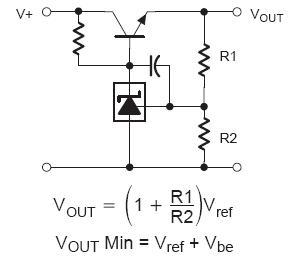
What is the role of this capacitor, soft start or maybe miller compensation ?
And haw to calculate correct value of this capacitor. (V+=15V and Vout=12V; Io=0.2A). Or maybe this capacitor is pick up empirically, but then whit values I should start off.
 

pass regulator

Hi,
The capacitor is used to bypass the ripple to the reference input so that the internal amplifier reduces the output ripple by negative feed back. The value of C may be calculated to get Xc at ripple frequency to be one tenth of parallel combination of R2and R1.

Regards,
Laktronics
 

    jony130

    Points: 2
    Helpful Answer Positive Rating
softstart with tl431

You probably overrate the schematic drawing details. TI has two similar application circuits with external output transistor in the datasheet, one has no compensation capacitor, the other has 10 nF. Actually, the need for compensation depends on the output load, but TL431 already has a first order frequency response that may achieve stability in many cases.
 

    jony130

    Points: 2
    Helpful Answer Positive Rating
schematic tl431 regulator

Oki. This schema is from Philips datasheet.
But I have another question, in Hitachi datasheet I found this diagram

It seems to me that gain equation is wrong. What you think about that
 

tl431 regulator application

Hi,
I too think it is wrong and should have been R1/R3.

Regards,
Laktronics
 

schema de tl431

Code:
Oki. This schema is from Philips datasheet
The TL431 design is orginated from TI. However, in the same datasheet, you find 0.1 uF capacitors using the same polarized symbol.
 

series pass regulator tl431

Thanks for help. I'm gonna tray this circuit and see how it's performed.
 

Status
Not open for further replies.

Part and Inventory Search

Welcome to EDABoard.com

Sponsor

Back
Top