b01010101
Junior Member level 1
My design is implemented on MAX7256AE.
I use QuartusII to systhesis and fit the design. The Classic Timing Analythesis reports that the fmax of the clk can get 84.03MHz, and no error or warnings are
reported.
I take timing simulation in Modelsim-SE6.2b and encounter with this error:
// Error Message //
# ** Error: D:/Modeltech_6.2b/win32/../altera/verilog/src/max_atoms.v(2070): $setup( datain:379100 ps, posedge clk &&& reset:381200 ps, 2900 ps );
# Time: 381200 ps Iteration: 0 Instance: /testcase/inst_harness/u_FCT/\r_addr[4]\/preg
# ** Error: D:/Modeltech_6.2b/win32/../altera/verilog/src/max_atoms.v(2070): $setup( datain:379100 ps, posedge clk &&& reset:381200 ps, 2900 ps );
# Time: 381200 ps Iteration: 0 Instance: /testcase/inst_harness/u_FCT/\r_addr[5]\/preg
.
.
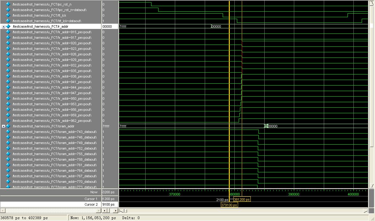
All the errors occur in 381200 ps, the waveform is attatched below (ft_lck is the clock):
Q1: I don't understand why this error occurs. It's only a simple asynchronous reset when 'pc_rst_n' is low. Why it can't meet the setup time?
I find that this error will not happen if I move the pc_rst_n some ns earlier or later. But why the error happens in some situation?
Why the Classic Timing Analysis didn't report this problem?
The code is just so common. Part of the source code is shown below:
// Source Code //
always @(negedge ft_lck or negedge pc_rst_n) begin
if(~pc_rst_n) begin
......
r_addr<=19'h0;
......
end
else begin
......
r_addr<=......;
......
end
end
By the way, I have 2 more questions:
Q2: What do "~dataout" and "~pexpout" mean in the waveform respectively?
Q3: Why "sram_addr~743_dataout" is before "sram_addr", but "ft_lck~dataout" is after "ft_lck"?
I use QuartusII to systhesis and fit the design. The Classic Timing Analythesis reports that the fmax of the clk can get 84.03MHz, and no error or warnings are
reported.
I take timing simulation in Modelsim-SE6.2b and encounter with this error:
// Error Message //
# ** Error: D:/Modeltech_6.2b/win32/../altera/verilog/src/max_atoms.v(2070): $setup( datain:379100 ps, posedge clk &&& reset:381200 ps, 2900 ps );
# Time: 381200 ps Iteration: 0 Instance: /testcase/inst_harness/u_FCT/\r_addr[4]\/preg
# ** Error: D:/Modeltech_6.2b/win32/../altera/verilog/src/max_atoms.v(2070): $setup( datain:379100 ps, posedge clk &&& reset:381200 ps, 2900 ps );
# Time: 381200 ps Iteration: 0 Instance: /testcase/inst_harness/u_FCT/\r_addr[5]\/preg
.
.
All the errors occur in 381200 ps, the waveform is attatched below (ft_lck is the clock):
Q1: I don't understand why this error occurs. It's only a simple asynchronous reset when 'pc_rst_n' is low. Why it can't meet the setup time?
I find that this error will not happen if I move the pc_rst_n some ns earlier or later. But why the error happens in some situation?
Why the Classic Timing Analysis didn't report this problem?
The code is just so common. Part of the source code is shown below:
// Source Code //
always @(negedge ft_lck or negedge pc_rst_n) begin
if(~pc_rst_n) begin
......
r_addr<=19'h0;
......
end
else begin
......
r_addr<=......;
......
end
end
By the way, I have 2 more questions:
Q2: What do "~dataout" and "~pexpout" mean in the waveform respectively?
Q3: Why "sram_addr~743_dataout" is before "sram_addr", but "ft_lck~dataout" is after "ft_lck"?