uranyumx
Advanced Member level 4
Hello,
I have tried to implement a for-loop with timer interrupt controlled. Because, I expect that the loop would run in a certain amount of time. For doing this purpose, I set a timer,
Then, in the "void HAL_TIM_PeriodElapsedCallback(TIM_HandleTypeDef *htim){ " function, I set a flag,
Lastly, in the while loop, I run my main code and reset the flag,
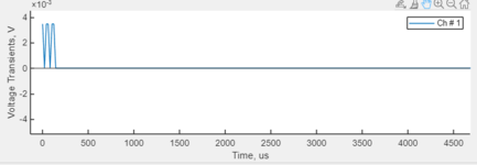
Then, I got a this signal. I expected that signal generate during 10 ms and it should have 200 us intervals. The parameters are pulse widths 200us, interphase is 100us, and frequency is 1500 Hz.
I have tried to implement a for-loop with timer interrupt controlled. Because, I expect that the loop would run in a certain amount of time. For doing this purpose, I set a timer,
Code:
static void MX_TIM4_Init(void)
{

  /* USER CODE BEGIN TIM4_Init 0 */

  /* USER CODE END TIM4_Init 0 */

  TIM_ClockConfigTypeDef sClockSourceConfig = {0};
  TIM_MasterConfigTypeDef sMasterConfig = {0};

  /* USER CODE BEGIN TIM4_Init 1 */

  /* USER CODE END TIM4_Init 1 */
  htim4.Instance = TIM4;
  htim4.Init.Prescaler = 96-1; // The processor core clock freq is 96 MHz
  htim4.Init.CounterMode = TIM_COUNTERMODE_UP;
  htim4.Init.Period = 1000-1; // 1kHz expected
  htim4.Init.ClockDivision = TIM_CLOCKDIVISION_DIV1;
  htim4.Init.AutoReloadPreload = TIM_AUTORELOAD_PRELOAD_DISABLE;
  if (HAL_TIM_Base_Init(&htim4) != HAL_OK)
  {
    Error_Handler();
  }
  sClockSourceConfig.ClockSource = TIM_CLOCKSOURCE_INTERNAL;
  if (HAL_TIM_ConfigClockSource(&htim4, &sClockSourceConfig) != HAL_OK)
  {
    Error_Handler();
  }
  sMasterConfig.MasterOutputTrigger = TIM_TRGO_RESET;
  sMasterConfig.MasterSlaveMode = TIM_MASTERSLAVEMODE_DISABLE;
  if (HAL_TIMEx_MasterConfigSynchronization(&htim4, &sMasterConfig) != HAL_OK)
  {
    Error_Handler();
  }
  /* USER CODE BEGIN TIM4_Init 2 */

  /* USER CODE END TIM4_Init 2 */

}
Then, in the "void HAL_TIM_PeriodElapsedCallback(TIM_HandleTypeDef *htim){ " function, I set a flag,
Code:
void HAL_TIM_PeriodElapsedCallback(TIM_HandleTypeDef *htim){
    if (htim == &htim4 && Burst == 1)
        {
            Flag = 1;
        }
}
Lastly, in the while loop, I run my main code and reset the flag,
Code:
if (Flag){
    HAL_GPIO_WritePin(Electrode_1st_Stim_GPIO_Port, Electrode_1st_Stim_Pin, GPIO_PIN_SET);
        if (CFirstPol == 1){
            HAL_GPIO_WritePin(Phase_2nd_GPIO_Port, Phase_2nd_Pin, GPIO_PIN_SET);
            DWT_Delay_us(pulse_width);
            HAL_GPIO_WritePin(Phase_2nd_GPIO_Port, Phase_2nd_Pin, GPIO_PIN_RESET);
            DWT_Delay_us(interphase);
            HAL_GPIO_WritePin(Phase_1st_GPIO_Port, Phase_1st_Pin, GPIO_PIN_SET);
            DWT_Delay_us(pulse_width2);
            HAL_GPIO_WritePin(Phase_1st_GPIO_Port, Phase_1st_Pin, GPIO_PIN_RESET);
        }
        else if (AFirstPol ==1){
            HAL_GPIO_WritePin(Phase_1st_GPIO_Port, Phase_1st_Pin, GPIO_PIN_SET);
            DWT_Delay_us(pulse_width);
            HAL_GPIO_WritePin(Phase_1st_GPIO_Port, Phase_1st_Pin, GPIO_PIN_RESET);
            DWT_Delay_us(interphase);
            HAL_GPIO_WritePin(Phase_2nd_GPIO_Port, Phase_2nd_Pin, GPIO_PIN_SET);
            DWT_Delay_us(pulse_width2);
            HAL_GPIO_WritePin(Phase_2nd_GPIO_Port, Phase_2nd_Pin, GPIO_PIN_RESET);
        }
        HAL_GPIO_WritePin(Electrode_1st_Stim_GPIO_Port, Electrode_1st_Stim_Pin, GPIO_PIN_RESET);
        DWT_Delay_us(off_per);
        DWT_Delay_us(IntBurstInterval);
        Flag = 0;
}
Then, I got a this signal. I expected that signal generate during 10 ms and it should have 200 us intervals. The parameters are pulse widths 200us, interphase is 100us, and frequency is 1500 Hz.