Continue to Site

Welcome to EDAboard.com

Welcome to our site! EDAboard.com is an international Electronics Discussion Forum focused on EDA software, circuits, schematics, books, theory, papers, asic, pld, 8051, DSP, Network, RF, Analog Design, PCB, Service Manuals... and a whole lot more! To participate you need to register. Registration is free. Click here to register now.

Timed Extractor Fan Circuit - how does this work?

Status
Not open for further replies.

Bluffer

Newbie level 6
Joined
Sep 24, 2012
Messages
12
Helped
0
Reputation
0
Reaction score
0
Trophy points
1,281
Location
England
Activity points
1,391
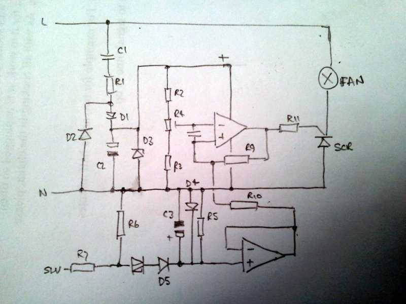
My bathroom extractor fan failed. I took it apart and found a burned component. I was interested to see how the circuit worked in order to spec the replacement part so I drew the circuit diagram below. Trouble is I can't figure it out and really need some help. Could you describe the operation of this circuit in a helpful paragraph? Please? A high level overview sort of explanation to get me started is what I'd like. Many thanks...:)

L=240VAC
Ls=240VAC supplied by switch
N=Neutral

bathroom fan.png
 

I've redrawn it in more conventional fashion. Q1 is an SCR not a triac and D3 is a Zener diode. U1 senses rectified mains from the switch input, buffers it to lessen the load on timing capacitor C3 then feeds it to comparator U2. The voltage is compared with that from the potentiometer to decide how long it has to decay before switching off.

If R11 has burned, the SCR is almost certainly faulty (fan running all the time or buzzing?) and there is a good chance U2 has cooked as well. Normally the voltage across R11 will only be about 5 - 6V when thew fan is running and the current through it only a few mA.

Brian.
 
Thanks Brian. Food for thought.

The unit is completely dead.

Could I see your redrawn circuit?

Ed
 

Thank you.

I'm confused about a part of the operation.

Current flows through R7 and D5 producing a potential across R5 which is measured as positive at the the non-inverting input to the op-amp. When current flows in the reverse direction no current can flow through D5 which would mean there is zero volts at the non-inverting input of the op-amp. This doesn't make sense to me because my simulation shows a small (mv) potential at the non-inverting input at all times the circuit is operating.

Is C3 able to discharge enough through R5 to keep the non-inverting input positive throughout the whole negative cycle?
 

C3 and R5 are the components that set the run time when the switch is turn off. With the values you have found, the time constant is about 20 minutes so there's no need to worry about half mains cycles!
C3 is kept charged up whenever the switch is on, possibly D4 is a Zener diode to prevent it charging to excesive voltage. It's the slow decay of voltage across C3 when the switch is off that lets you adjust the 'over run' time.

Brian.
 

How can I roughly calculate the voltage to which C3 charges? I assumed it was something like 220/220,000 * (1/ 2.pi.50.470x10-6) which gives 7mV but my circuit simulator shows it charges to 1.3V.

Ed
 

It's difficult to say without knowing someo of the othe rcomponent values so some guesswork is needed:

Firstly the 240V is halved byt the potential divider R6 and R7 so it can't go above 120V AC at their junction. Then there is the Diac (if it is one) which probably drops around 30V so we are down to 90V AC. Next there is the rectifier D5 and load resistor R5 and the diode I suspect is a Zener. Because R7 is a high value, the current that can be drawn at C3/D4.R5 is relatively low and the Zener current will stabilize the voltage at that point. So the maximum voltage with "SW" live will be the Zener breakdown voltage of D4. I would hazard a guess it will be around 12V but you would have to read it's part number to be sure.

Brian.
 

Sorry I was working from a later revision of the circuit, with more component values on it, when I asked that question.

I'm wondering now what is the function of the capacitor C4? Is it smoothing the inputs to U1B?

And could it be possble that the SCR is, in fact, a triac? I ask because the part number is Z0405MF. I think I understand why it shouldn't be - because if it were then a positive OR negative current at its gate would trigger it whereas a SCR would only be triggered by a positive output from U1B?

And what is the point of using a DIAC in this circuit?
 

Attachments

  • Bathroom Fan r03.pdf
    50.2 KB · Views: 116
Last edited:

I'm guessing C4 is there to slow the response of the comparator (U1B) so it doesn't produce rapid pulses at the transition from one state to the other although R9 is also there for a similar purpose.

The switch device is a triac. In these units the fan works on DC but the firing circuit can only make it conduct in one direction so an SCR would work equally well. There is further confirmation of this in the LED which would be destroyed if reverse polarity was applied to it. It is actually a 4A/600V triac with 5mA gate sensitivity made by ST micro. Incidentally, this means R11 cannot be more than 2K in value and is probably quite a bit less.

I'm not sure why the diac is used, all it does it drop the voltage. Perhaps the designer added it to lessen the chances of noise on the switch line upsetting the timing circuit.

Brian.
 

On closer inspection I think that what I thought was an LED is actually a miniature bulb. Actually it looks neither like a bulb or LED that I'm familiar with...

2012-11-01 17.13.54.jpg

I assumed that the motor / fan is AC because the triac can conduct in both directions with a positive (or negative) gate current.

As I can't tell for sure the value of Zener D3 I will have to guess what value of R11 to use to get this circuit working again but 2k seems like a good starting place.
 
Last edited:

Thats a neon lamp - and it will work on DC or AC. Basically a pair of electrodes in a glass bubble full of neon gas. When the voltage across it reaches about 90V. the gas ionizes, it starts to conduct and it glows orange.

Incidentally, if one electrode glows but not the other, it's working on DC, if they both glow it's AC.

Brian.
 

I replaced R11 with a 1k and powered up the circuit. R11 burned out immediately. I removed R11 and put my ammeter in its place. This read 0.1A and provided enough gate current to switch the triac on and the fan and lamp. So I guess the triac is OK and the fault lies with the Op Amp output?

The zener voltages at D4 is 6.7V and D3 is 8V which means that the maximum positive output from U1B should be 8V. However then I noticed that the ground pin of LM324N (not LM324AD as shown in the circuit diagram) is connected to Neutral. How can this be, surely this would destroy the op amp?
 

If you connected an ammeter instead of the 1K resistor it has kllled the op-amp anyway. The ammeter probably only has a resistance of one or two ohms!

What puzzles me is that an LM324 running on an 8V supply can only possibly make (I = V/R) = 8mA flow through the resistor so it would dissipate at most 64mW of heat which would be un-noticable. The current must be coming through the fan and triac and be being dumped into the op-amp output. That would mean the triac and op-amp both need replacing. The op-amps cost pennies but the triac will be a bit more.

Brian.
 

Unfortunately I also stuck a screwdriver into the spinning fan breaking a blade off and it turns out that a mechanical device attached to a relay used to open the fan shutters is also broken so this repair / education project is purely educational now!

I am still curious about the neutral connection to the Gnd pin on the LM324. Surely 240VAC will destroy the Op-amp but I've triple checked and the circuit does appear to be wired this way. What am I missing?
 

You can connect the ground to neutral or live or anything else for that matter, it's only the voltage to the other pins RELATIVE to the ground pin that matters. The IC doesn't realize that it's ground isn't zero volts. In this simple circuit, the IC thinks neutral is ground and it uses C1/R1/D1/D2/D3 and C2 to derive a positive supply rail from the live wire. Incidentally, C1 is probably 100nF not 100uF.

Be careful using it as an educational toy, it can be lethal with those voltages on it!

Brian.
 

I'm aware of the risks and take great care! Thanks for the warning though, it is worth pointing out.

You could well be right about the value of C1, I guessed it since it is not visible on the capacitor body.

Now, I understand what you say about the positive supply rail being derived from C1/R1/D1/D2/D3/C2 - the positive voltage supplied to the op-amp will be a DC voltage in the region of 6V. However, the ground pin of the op-amp is connected directly to the neutral of an alternating 240V supply! At some point the voltage at the ground pin of the op-amp will be around 339V relative to zero. I'm clearly missing something here and I'm sorry but I didn't understand your explanation. Would you please try again to help me clarify this point?
 

What's missing is that there is no 'zero'. True, the voltage could be very high (although Neutral is actually joined to Earth somewhere between you and the electricity sub-station) but that doesn't matter. If the ground of the op-amp is at 300V relative to Earth and the supply pin is at 310V, the IC is still happy because it thinks there is only 10V across it. Similarly, it the ground pin was at -300V relative to Earth and the supply was at -290V it would still have 10V across it.

Bear in mind there is no Earth connection to your circuit (nor should there be) so absolute potentials above or below zero are irrelevant, only the difference between connections matters.

C1 is actually responsible for dropping the bulk of the AC down to a more usable level. Capacitors have 'reactance' which is similar to resitance in a DC circuit. 100nF (0.1uF) has a reactance at 50Hz of about 32K Ohms. If you were to use a resistor in t's place it would work equally well but instead of running cold it would produce about 2W of heat and have to be fairly large.

Brian.
 

That's an interesting point you make about C1.

In your example where the ground of the op-amp is at 300V relative to Earth and the op-amp supply pin is at 310V; the IC is happy because it has a potential difference of 10V across it. However in my circuit it appears that the LM324 supply pin is at a constant 6 Volts (ish) relative to Earth and the op-amp ground pin, attached to the power supply neutral, is fluctuating between +/- 330V giving a potential difference of several hundred volts. Sorry I still don't get it.
 

You're getting me confused as well now !

You have two test meter probes, where exactly are you connecting them when measuring these voltages?

Brian.
 

Status
Not open for further replies.

Part and Inventory Search

Welcome to EDABoard.com

Sponsor

Back
Top