Continue to Site

Welcome to EDAboard.com

Welcome to our site! EDAboard.com is an international Electronics Discussion Forum focused on EDA software, circuits, schematics, books, theory, papers, asic, pld, 8051, DSP, Network, RF, Analog Design, PCB, Service Manuals... and a whole lot more! To participate you need to register. Registration is free. Click here to register now.

Time multiplexing and refresh rate calculation by counter

Status
Not open for further replies.

shikharmakkar

Junior Member level 1
Joined
Apr 11, 2013
Messages
18
Helped
0
Reputation
0
Reaction score
0
Trophy points
1,281
Activity points
1,427
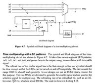
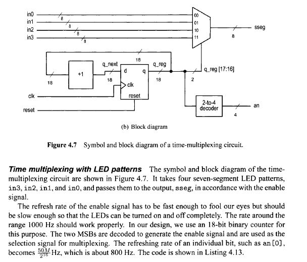
I was going through a verilog code for time multiplexing with LED patterns. I am attaching the screenshot of the problem. I could not understand why they took the 18 bit counter because that would divide the frequency by 2^18 and not 2^16.
 

the counter msbits[17:16] changes for every 2^16 counts.

that selects your in0 ... in3.
 

I could not understand why they took the 18 bit counter because that would divide the frequency by 2^18 and not 2^16.

I agree with your calculation. The refresh rate with an 18 Bit counter is 200 Hz, not 800 Hz.
 

The text in the screenshot is confusing. One digit at a time is on and the change rate is 800 Hz. Each digit is only on for one of every four 800 clock cycles. This means that the update rate for the complete display is 200 Hz, which corresponds to an 18-bit counter. The enable signal for each digit will be a 200 Hz signal with 25% duty cycle.

The human eye can only detect flashing up to about 50-70 Hz, so 200 Hz will be a steady light.

- - - Updated - - -

Edit: It should be "one of every four 800 Hz clock cycles".
 

Status
Not open for further replies.

Part and Inventory Search

Welcome to EDABoard.com

Sponsor

Back
Top