Continue to Site

Welcome to EDAboard.com

Welcome to our site! EDAboard.com is an international Electronics Discussion Forum focused on EDA software, circuits, schematics, books, theory, papers, asic, pld, 8051, DSP, Network, RF, Analog Design, PCB, Service Manuals... and a whole lot more! To participate you need to register. Registration is free. Click here to register now.

Time-domain simulation for frequency controlled resistor

Status
Not open for further replies.

farshaddd

Newbie level 5
Joined
Jun 7, 2021
Messages
10
Helped
0
Reputation
0
Reaction score
0
Trophy points
1
Activity points
86
Hello everyone.
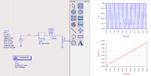
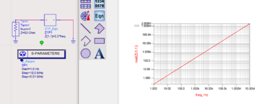
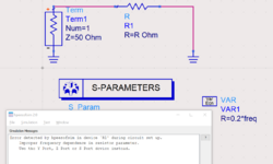
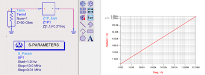
I have a resistor that is defined as:
R=0.2*f
where f is the frequency of the resistor voltage or current.
My problem is that how can I define this resistor in my transient (Time domain) simulations in ADS or other software?
Thanks, everyone.
 

By itself a resistor keeps the same ohm value irrespective of frequency. Evidently this exercise asks you to construct a component or a circuit which changes its impedance depending on frequency. This probably means reactive impedance, which involves using time-dependent components. A resistor or two also is needed, most likely.


A long time ago in a galaxy far, far away I made a veriloga frequency-to-voltage model.

You could use that to control a voltage dependent resistor model.

Or you could combine the two all in a veriloga bundle.

The frequency sense was crude, just a zero crossing math, latest minus previous timeX, reciprocal, value -> output voltage. It needs a clean single tone to get a sane value.
 
Tony, don't confuse him ... inductor has jX scaling with frequency, not real part (R) scaling with frequency. Very different behaviour.
I thought about an inductor, too. ...but it has phase shift and no real part (ideally).

I know the topic is about simulation...
But I wonder: is it possible to build a true "frequency dependent resistor"? .. that can handle a multi frequency signal input and treat each frequency according the given formula?

Klaus
 

But I wonder: is it possible to build a true "frequency dependent resistor"? .. that can handle a multi frequency signal input and treat each frequency according the given formula?

Yes, if the simulator supports SnP Touchstone files you can insert arbitrary impedance vs. frequency values using the method that I described above.
--- Updated ---

Another option in ADS is to use Z1P_Eqn from palette "Eqn based linear"

This works for frequency domain simulation (obviously) and also for transient simulation.
 

Attachments

  • ads_rvar_tran.png
    ads_rvar_tran.png
    95.9 KB · Views: 149
  • ads_z_vs_freq.png
    ads_z_vs_freq.png
    61.3 KB · Views: 148
Last edited:
By itself a resistor keeps the same ohm value irrespective of frequency. Evidently this exercise asks you to construct a component or a circuit which changes its impedance depending on frequency. This probably means reactive impedance, which involves using time-dependent components. A resistor or two also is needed, most likely.
Hi BradtheRad
This resistance is the modeling of the skin effect of an RF choke and is necessary to model it by one resistor.
 

You can also model this using a Touchstone S1P file. Just provide a few frequency points and specify linear interpolation. For the format you can use "Z" and then enter the impedance directly, instead of S-params.


! frequency dependent resistor
# HZ Z RI R 50
1 0.2 0
10 2 0
100 20 0
1000 200 0

Hi volker@muehlhaus

I appreciate your response.
Fortunately, the coilcraft company has produced touchstone files for the RF Chokes by measurements, but the frequency range is from 30 kHz to 90 MHz. The DC operation is also important for me too. So my question is that can I add s-parameter data in DC (0Hz) to the reported S2P files? The schematic is also given by the company for RF Choke. I have attached the schematic file. As it is clear from the schematic, values of all elements are constant but Rvar is variable with frequency.
Thanks a lot.
 

Attachments

  • Doc1.pdf
    66.7 KB · Views: 105

I'm a bit confused by the original statement that you
"have a resistor that is defined as: R=0.2*f" because
that's not a resistor and I'm curious how you came to
have (implying physical possession) such a thing,
which I would not think exists.

I'm wondering whether it is in fact an inductor and
whoever told you the "definition" simply has ignored
the phase and the imaginary current, replaced |Z| with
"R" and sent you on a wild goose chase.

At any rate, since this appears not to be a classical
passive component I think the behavioral model is
likely the way through the problem. But getting a
valid, waveform-detail-robust instantaneous frequency
will be tricky (mine only updates on a zero crossing,
so "R" in the moment will be old news).
Hi dick_freebird
This resistance is the modeling of the skin effect of an RF choke. Actually, as the frequency increases, the electrons will flow through the skin of the conductor. So the resistance will increase.
 

So my question is that can I add s-parameter data in DC (0Hz) to the reported S2P files?

Yes, you can calculate S-params for DC and add that to the SnP file.

But have you tested if that is necessary? If there is no DC in the data, ADS will use extrapolation down to DC and that should be good enough. The difference between 30kHz choke resistance and DC is almost nothing. You worry about an effect that is not relevant in real world RF design.

Side note: I don't like that skin effect model with a frequency dependent resistor. For the models that I extract, skin effect is modelled by parallel R and L, which have fixed values. That gives a reasonable agreement for R(f) and L(f) with no such modelling issues.
 
Last edited:
Yes, you can calculate S-params for DC and add that to the SnP file.

But have you tested if that is necessary? If there is no DC in the data, ADS will use extrapolation down to DC and that should be good enough. The difference between 30kHz choke resistance and DC is almost nothing. You worry about an effect that is not relevant in real world RF design.

Side note: I don't like that skin effect model with a frequency dependent resistor. For the models that I extract, skin effect is modelled by parallel R and L, which have fixed values. That gives a reasonable agreement for R(f) and L(f) with no such modelling issues.
Thank you. I appreciate your reply.
 

Skin effect can be modelled in the first order by a sqrt(f) proportional resistor, as in the Coilcraft application note quoted in post #10. Behavioral component definitions of this kind (impedance as a function of complex frequency s) as well as table definitions (e.g. S2p) are translated to time domain by means of Laplace respectively fourier transform. LTspice can do it, I presume also ADS.

The behavioral definition already includes the DC case (s = 0), also tables can be extrapolated because skin impedance converges to zero. Fourier transform however involves a limitation in number of points and respectively ratio between highest and lowest signal frequency. Parameters have to be chosen with caution to avoid artefacts. High end tools like ADS are hopefully freeing the user from thinking about parameters.

For the given problem, I presume that coil resistance variation below 30 kHz can be simply ignored.
 

If "Frequency" has been defined in a source, you can add the same parameter into Resistor's field.
Use VAR Block.
 

If "Frequency" has been defined in a source, you can add the same parameter into Resistor's field.
Use VAR Block.
Sure? I suggested the "complicated" way above because that simple R=0.2*freq doesn't work.
 

Attachments

  • R_freq.png
    R_freq.png
    54.4 KB · Views: 146

Sure? I suggested the "complicated" way above because that simple R=0.2*freq doesn't work.
It does not work in s-parameters analysis since "freq" variable is not defined.Because "freq" parameter is a reserved one.
But it works in HB if it's defined as local parameter.
1624352508000.png
1624352530430.png


1624352763261.png
 
Last edited:

It does not work in s-parameters analysis since "freq" variable is not defined.

I don't agree. "freq" is available in S-parameter analysis and returns the simulation frequency. But it is restricted what component parameters can be scaled using "freq" ... exactly as the ADS error message in post #18 says.

Your attachment link is broken.
 

Attachments

  • sparam_freq.png
    sparam_freq.png
    252.1 KB · Views: 111
Last edited:

Status
Not open for further replies.

Part and Inventory Search

Welcome to EDABoard.com

Sponsor

Back
Top