Continue to Site

Welcome to EDAboard.com

Welcome to our site! EDAboard.com is an international Electronics Discussion Forum focused on EDA software, circuits, schematics, books, theory, papers, asic, pld, 8051, DSP, Network, RF, Analog Design, PCB, Service Manuals... and a whole lot more! To participate you need to register. Registration is free. Click here to register now.

Three Phase AC Induction motor Control [PIC]

Status
Not open for further replies.

Okada

Banned
Joined
Jun 16, 2016
Messages
1,159
Helped
129
Reputation
252
Reaction score
129
Trophy points
63
Activity points
0
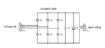
I have to implement Constant V/F for a Three Phase Induction Motor. I am referring Microchip AN900 application note.

I need 6 SPWM signals.

I have configured the registers like these.

1. I want to know if I have to use a sine table with duties for 180 degrees or 360 degrees ?

2. If 180 degrees can be used then how to invert the PWM signals that is say I want to invert PWM0 after 180 degrees then how to do that ?

3. If 360 degrees can be used then how to generate the values for 360 degrees sine table. I used

https://tahmidmc.blogspot.in/2012/10/smart-sine-software-to-generate-sine.html

software but for 360 degrees it generates some negative values and I can't use negative values in the PWm duty registers.


Code C - [expand]
1
2
3
4
5
6
7
8
9
10
11
12
13
14
15
16
17
18
19
20
21
22
23
24
25
26
27
28
29
30
31
32
33
34
35
36
// PWM Control module enable configuration
 
    // PWM timer control register configuration
    PTCON0 = 0x02; // PWM timer control register 0 configured in the free running mode, 1:1 postscale,Fosc/4 (1:1 prescale)
    PTCON1 = 0x80; // PWM timer control register 1 with PWM time base timer bit enabled
 
    //PWM control register configuration
    PWMCON0 = 0x40; // PWM0, PWM1, PWM2, PWM3, PWM4 and PWM5 pins are enabled for PWM output
    PWMCON1 = 0x00;
 
    // Dead time control register
    DTCON = 0x00;           //  dead time disabled
 
    //Output override control register
    OVDCOND = 0xFF;     //  Output on PWM I/O pin is controlled by the value in the corresponding POUT bit
 
    // Output state register
    OVDCONS = 0x00;     //  Output on PWM I/O pin is inactive when the corresponding PWM output override bit is cleared
 
    //Fault configuration register
    FLTCONFIG = 0x00;   //  disable fault detection feature
 
    // PWM time base registers
     PTMRL = 0x7D;          //  PWM time base register (lower 8 bits)
     PTMRH = 0x00;          //  PWM time base register (upper 4 bits)
 
 
    //PWM time base period registers are set to get 20kHz PWM frequency
     PTPERL = 0x7D;         //  PWM time base period register (lower 8 bits)
     PTPERH = 0x00;         //  PWM time base period register (upper 4 bits)
 
    // PWM special event trigger compare registers
    SEVTCMPL = 0x00;
    SEVTCMPH = 0x00;
 
    // PWM Duty cycle registers


In this equation what is PTMRPS ?

TPWM = (PTPER + 1) x PTMRPS / Fosc/4

I am referring PIC18F4431 datasheet page no. 193. I need to calculate PTMRL and PTMRH values ? How to calculate it ?

I am using 20 MHz Crystal and I need 10 or 20 KHz PWM frequency.

Is it PTMR Post Scalar ? If yes, I have set Post Scalar to 1:1. Then what value should I use for PTMRPS ? 1?


PTPER + 1 = (TPWM * Fosc/4) / PTMRPS

My PTMR Post Scalar is 1:1

Fosc is 20 MHz

Fosc / 4 = 5 MHz

Required PWM frequency is 20 KHz

TPWM = 50 us

So,

PTPER + 1 = 50u * 50 M / 1 = 250

PTPER = 249

Is this right ?

- - - Updated - - -

See attached image. This is my circuit. I am not getting any PWM signals. Proteus file attached and also source code.

- - - Updated - - -

Edit: I got the 6 PWM signals. I had to use 8-bit PWm duties.
 

Attachments

  • Three Phase AC Induction Motor Control.rar
    24.7 KB · Views: 146
  • Three Phase Induction Motor Control.png
    Three Phase Induction Motor Control.png
    33.3 KB · Views: 143
Last edited:

This is related to the same project and hence I am asking the question here.

This is my Three Phase bridge Rectifier Circuit to get 560 V DC BUS voltage for the 3-Phase Induction Motor Driver.

I have chosen 1600 V 45 A Three Phase bridge Rectifier. My Motor draws max 18 Amps.

In the circuit what value capacitors I can use ?

- - - Updated - - -

I am not able to find Capacitor rated 220 uF or 330 UF 600V or above. However I find 0.i uF 1 KV Ceramic. Please help me find the right capacitor for the bridge rectifier.
 

Attachments

  • Three Phase Bridge Rectifier.png
    Three Phase Bridge Rectifier.png
    25 KB · Views: 148
  • vs-40mt160p-p-849714.pdf
    271.5 KB · Views: 103

Hi

Although, their are two important parameters to consider when choosing a suitable smoothing capacitor and these are its Working Voltage, which must be higher than the no-load output value of the rectifier and its Capacitance Value, which determines the amount of ripple that will appear superimposed on top of the DC voltage.

Too low a capacitance value and the capacitor has little effect on the output waveform. But if the smoothing capacitor is sufficiently large enough (parallel capacitors can be used) and the load current is not too large, the output voltage will be almost as smooth as pure DC. As a general rule of thumb, we are looking to have a ripple voltage of less than 100mV peak to peak.

The maximum ripple voltage present for a Full Wave Rectifier circuit is not only determined by the value of the smoothing capacitor but by the frequency and load current, and is calculated as:


Full wave rectifier
Vripple = Iload / 2 f C

Half wave rectifier
Vripple = Iload / f C

3 phase rectifier
Vripple = Iload / 6 f C
 
Last edited:
  • Like
Reactions: Okada

    Okada

    Points: 2
    Helpful Answer Positive Rating
The 3-Phase bridge Rectifier Supplies 560V DC VBUS Voltage to 3-Phase AC Induction motor Driver and Motor Current max is 18 Amps.

So, I have to take Iload as 18 Amps ?

f is 50 Hz (3-Phase In frequency)

Vripple = 560V ?

C = Iload / (Vripple * 6 f ) ?
 

Assume that we want to make a 9V, 500mA power supply using the LM7809 voltage regulator device, 12V transformer, bridge rectifier and filter capacitor. Line frequency is 50hZ. How large should we make the filter capacitor?

From the spec sheet, we learn that the dropout voltage of the LM7805 is 2.5V. Therefore, the valley of the peak-to-peak ripple should be 9V + 2.5V = 11.5V.

Assuming that the average rectified DC voltage is 12VDC, the minimum negative peak of the ripple voltage = 12V – 11.5V = 0.5V. The peak-to-peak ripple voltage is double the peak or 1.0V and we use 70% factor. Plugging it into the formula:

C = 0.7 * I /(ΔV * F) = 0.7 * 0.5A /(1Vp-p * 100hZ) = 0.0035farads or 3500µf
 
  • Like
Reactions: Okada

    Okada

    Points: 2
    Helpful Answer Positive Rating
Imax = 18A
Output of 3-Phase Bridge rectifier is 560V (from 400V AC 3-Phase input)

Let us assume that the valley of peak-to-peak ripple should be 550V

for 70%

Vp-p = 560 - 550 = 10V

C = 0.7 * I / (ΔV * F) = 0.7 * 18A / (10Vp-p * 100hZ) = 12.6 / 1000 = 0.0126farads = 12600 uF

How to get this much Capacitance value using standard capacitors in parallel ? The VBUS voltage is 560V so I have to choose Capacitor voltage of 1 KV.
 

C = 0.7 * I / (ΔV * F) = 0.7 * 18A / (10Vp-p * 100hZ) = 12.6 / 1000 = 0.0126farads = 12600 uF

It formula is for single phase full bridge. You would use 300Hz for three phase.


As per your case:

Power factor = 0.8 or 80%
Current = 18A
Vpp = 10v
Frequency = 50Hz

C = iload / ( Vpp * 6F )
C = (18*0.8) / (10 * 50*6)
C = 14.4 / 3000
C = 0.004666 farads
C (µf) = 0.004666 * 1000000 = 4666µf

Finally we find our filter capacitor value is 4666µf(more then 600VDC)
 
Last edited:
  • Like
Reactions: Okada

    Okada

    Points: 2
    Helpful Answer Positive Rating
Full wave rectifier
Vripple = Iload / 2 f C

Half wave rectifier
Vripple = Iload / f C

3 phase rectifier
Vripple = Iload / 6 f C

So the ripple voltage is reduced for 3 phase. That is an important point.

You also need to focus on the ripple frequency. For a three phase rectification, the ripple frequency is higher and a smaller capacitor would do. For a motor like the one you are going to run, a small capacitor is good enough.
 
  • Like
Reactions: Okada

    Okada

    Points: 2
    Helpful Answer Positive Rating
I am not connecting capacitor to motor. Capacitor is for filtering 560V DC VBUS voltage. The motor is driven by 6 Power Mosfets with 6 PWM signals.
 

So the ripple voltage is reduced for 3 phase. That is an important point.

Yes...you are right. Even as frequency increases corresponding capacitor value will be decrease proportionally.
 

If I add 2x 1000 uF 350V DC Capacitors in Series then the Capacitance will reduce but can I then apply 450V DC across the series capacitance as the voltage will be 350 + 350 V ?
 

If I add 2x 1000 uF 350V DC Capacitors in Series then the Capacitance will reduce but can I then apply 450V DC across the series capacitance as the voltage will be 350 + 350 V ?

Right; but also use resistors (in parallel with the capacitors) that will help divide the load voltage (share the voltage equally between the caps). I guess 100K should be good enough and they will also act to bleed any residual charges.
 

It is not good, because if any capacitor damaged/weak no role of your second capacitor will be.

When you connect capacitors in series, any variance in values causes each one to charge at a different rate and to a different voltage. The variance can be quite large for electrolytics. On top of that, once the bank is charged, each capacitor's leakage current also causes a *different* voltage across each capacitor. you add balancing resistors. Basically the resistors act as a big voltage divider and counteract the effects of variance in capacitance and leakage current. And if there is no leakage current, the capacitors must eventually become charged according to the voltage divider values.

After all i will indicate sideways to parallel capacitors with a conductor is best way.
 

Status
Not open for further replies.

Part and Inventory Search

Welcome to EDABoard.com

Sponsor

Back
Top