Continue to Site

Welcome to EDAboard.com

Welcome to our site! EDAboard.com is an international Electronics Discussion Forum focused on EDA software, circuits, schematics, books, theory, papers, asic, pld, 8051, DSP, Network, RF, Analog Design, PCB, Service Manuals... and a whole lot more! To participate you need to register. Registration is free. Click here to register now.

Thermostat with LCD Display

Status
Not open for further replies.

joeman112

Junior Member level 2
Joined
Jun 11, 2011
Messages
22
Helped
0
Reputation
0
Reaction score
0
Trophy points
1,281
Activity points
1,459
Hi,
I'm definitely a beginner with electronics, but had some experience with PIC's and my Job is a software engineer (using DSP).
So I am looking at making a thermostat for a IR heat lamp (D) (240V).
evcajs.jpg

A. Thermocouple used for feedback for D (heat lamp) & on LCD screen.
B. Thermocouple used for indication only on LCD Screen.
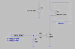
C. I realize i need some sort of component here. PIC will output a Discrete signal On/Off for heat lamp. Is this a relay to switch the 240V?
D. Heat Lamp.
E1 & E2. Would I need an ADC here for the thermocouple? or what form does the PIC receive the Thermocouple signal?

Please could you point out what components I would need to buy to amke this idea possible (i'm from the UK, but can search for component number or name).

I would be really grateful for any help/advice anyone can give me as this is a hobby project for a vivarium (reptile tank)

Many Thanks

Joe
 

Ok, So I made a parts list to the best of my ability.
Can anyone comment on this to make sure I will be doing things correctly?
Thanks, Joe
n1s17a.png
 

You are going to need a driver for the relay. It's typically a bad design to try to drive the relay coil directly from the microcontroller output pin for two reasons.

1. Coil current required to actuate the relay is typically close to or exceeds the microcontroller output sourcing capabilities.

2. The coil voltage for most of these relays is more than the I/O voltage of the microcontroller.

I would recommend the attached circuit.
 

Attachments

  • Relay_Driver_CKT.PNG
    Relay_Driver_CKT.PNG
    47.6 KB · Views: 103
I would recommend the attached circuit.

I can't see a circuit attached. Am I being stupid?

Also does the rest of it look ok?

---------- Post added at 22:09 ---------- Previous post was at 20:22 ----------

ahh yep i see the attachment now. Couldn't see it from my laptop.
So I understand the reasons for why I shouldn't/can't use the PIC output to drive the Relay.
What component is Q1? I understand that its like a logic gate, if the signal is high then close the contact on the 12V line to activate the relay.
thanks travulous
 

Q1 is a NPN transistor and it works as a low side switch to provide the gnd to the relay and turns it on only when the transistor base is high, it can be any model that can work with the intended relay current, for example 2n2222.
What is the operation voltage of your relay?
Depending on the available supply voltages in your project you should choose a relay that use that voltage too, for example if you have only 5v available then don't buy a 12v relay, on the other hand if you have both 5v and 12v supplies available then buy a 12v relay with uses less current.

Alex
 
Are you going to use the NTC for temperature measurement?
If so the resistance is very low (10 ohm) get a higher resistance model (like 1K) but you still need to know the resistance VS temperature curve and use it to calculate the temperature, the measured temperature will not be very accurte using the NTC.
You may get an lm35 which has a much higher accuracy and is already calibrated to give 10mV / degree Celsius.

EDIT: your NTC says 10R @170° so it will have a higher resistance in room temperature, what is your intended operation range(temperature)?

Alex
 
...for example if you have only 5v available then don't buy a 12v relay...
Just a remark : When same bus is shared to electronic and power devices, special care must be taken.
At specific case of 5V Relay instead 12V one, generated spike over bus, tends to be increased in a scale of 2,4 (=12/5)
That´s because regarding Lorentz law, in order to achieve same actuactor coil force, numbers of turns must increase, performing higher inductance.

+++
 

Thanks for all your replies and sorry for my late response.
alexan_e - Thanks for that, the range is 20 - 45 Celsius so the LM35 seems correct for the job! Many thanks - that has saved me time and money.

The board runs 5v. The heat lamp is 240v (100w) and i just want to switch it on. Can I use something similar to a 2N2222 to switch the 240v rather than a relay. £5 seems quite expensive just to turn a switch on.

What I am getting at is - is there an easier way to switch the heat lamp on?
 

You can probably use a triac which should be driven by an optocoupler for insulation but I think the relay is easier to use.
I have never used a triac but you can find some examples if you search the Internet, you can also take a look at a similar thread https://www.edaboard.com/threads/213071/

Your relay seems expensive, you should be able to find a a cheaper model, 100W in not so high.
I have made a search, is this your relay **broken link removed**
do you need a relay that has 4 switches?
also this is a relay that can work up to 250v input (to the coil), there is no need for that king of relay, select a relay for your specific voltage.
I found many relays in that site starting from £0.5 to 1.5
Relays & Switches | Relays | Electromechanical Relays

if you have a higher voltage available you should buy a higher voltage relay, for example if you have 7v and you use a regulator for the 5v then get a relay for the unregulated voltage (7v)

Alex


You can probably use a triac which should be driven by an optocoupler for insulation but I think the relay is easier to use.

This is a relay that can work up to 250v input (to the coil), there is no need for that king of relay

Ahh I was looking at the input voltage instead of the 240v switching voltage for the heat lamp. Whoops...Showing my lack of experience here.

So reading around, it seems that a Triac is the better/preferred option (no sparks & no noise).

Browsing for Triacs i found the following:
Toshiba | Optoelectronics and Displays | Optoelectronics | OptoCoupler | Thyristor/Triac Output |TLP3043(S,C,F,T)
I am a little confused by the naming conventions as it is under the "OptoCoupler" Heading - does this mean that it is a Triac and OptoCoupler in one package?
 

Your optocoupler has a triac in the output but it can't be used for what you want because it says "Maximum Continuous Output Current: 100mA", you need more than that so you should use an external triac but as I said I can't advice you any further, I haven't played around with these devices mainly because I do low voltage circuits.

Alex
 

Status
Not open for further replies.

Similar threads

Part and Inventory Search

Welcome to EDABoard.com

Sponsor

Back
Top