Continue to Site

Welcome to EDAboard.com

Welcome to our site! EDAboard.com is an international Electronics Discussion Forum focused on EDA software, circuits, schematics, books, theory, papers, asic, pld, 8051, DSP, Network, RF, Analog Design, PCB, Service Manuals... and a whole lot more! To participate you need to register. Registration is free. Click here to register now.

thermometer to binary encoder truth table

Status
Not open for further replies.

mohamed mahmoud

Junior Member level 1
Joined
Jan 31, 2014
Messages
16
Helped
0
Reputation
0
Reaction score
0
Trophy points
1
Visit site
Activity points
118
i,am working in designing time to digital converter . i need to know truth table for thermometer to binary encoder (31 to 5 bit) ??
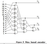
i will use mux based thermometer to binary encoder.
 

The required function is called priority encoder.

And tends to be bloody slow when you do a straight forward implementation of such. In the past I've flushed a fair amount of time into getting this fast for large bit vector. As in in the range of 128-256 bits. I tried to think of a clever notation, possibly with some forgenerate, but performance always made me a little sad. Only way I could get a couple hundred MHz out of it was to throw Ye Olde Brain at it, and hand craft multiple pipeline stages with LUTs in the first stages and adders in the later stages.

If anyone knows of an elegant & fast design I would be very much interested. And amusingly enough that pipelined design was also for a TDC. 31-bit is for wimps. ;-) Does your TDC also have to be bubble tolerant? That tends to make the design challenge more fun. ;-)

- - - Updated - - -

Update: just came across some scribbles^H^H^H^H^H^H^H^H^H design documents for a small test design. It reduces a 180-bit tdc line to an 8-bit number (values 0 - 180 obviously) and takes 7 pipeline stages.

I guess this here A4 is trying to guilt trip me into doing proper documentation. Well screw you piece of paper. Bottom of the pile for you!

now where was I ...
 

i decide to use max_based encoder **broken link removed**
the problem i has faced :
time to digital converter is block that convert time difference between two signals to digital code .
when time difference is 4 psec , i found the digital code is ''0000''.and
when time difference is 5 psec ,i found the digital code is ''0000''.and
when time difference is 6 psec ,i found the digital code is ''0000''.and
when time difference is 7 psec ,i found the digital code is ''0000''.
how can i distinguish between the time difference by this encoder ??
 

There's no attachment uploaded for whatever you wanted to show.

Why don't you just post the code? (with syntax tags...read this first )
 

mux.PNG

this is the topology of mux_based encoder that i use
 

No doubt that the encoder will work - with suitable digital input data. So apparently your TDC circuit doesn't generate the expected thermometer code.
 

No doubt that the encoder will work - with suitable digital input data. So apparently your TDC circuit doesn't generate the expected thermometer code.

i could n,t understand what you have said .
do you want to say that i need to change topology of encoder ??
 

In post #4, you describe input data as "time difference xx" but don't show the digital input to the encoder. We can just guess that it's not the expected thermometer code, otherwise you'd get correct output.
 

the time difference is converted to the thermometer code by some circuit and no problem in this generating digital input code .
the problem appear when i want to convert 15 bit to 4 bit by encoder.
 

What is the expected output for the quoted time delays in your post? For example: 4 ps, what do you think the binary output should be? Same question for 7 ps.

This is real hardware we are talking about right? Not some non-working simulation...
 
What is the expected output for the quoted time delays in your post? For example: 4 ps, what do you think the binary output should be? Same question for 7 ps.

This is real hardware we are talking about right? Not some non-working simulation...

thanks for your reply i will think again
thanks
 

So what is it that generates the input for the thermometer to binary encoder? Do you use real hardware? Or do you use a testbench to generate bit vectors? Or (and this is the potentially problematic part) do you also simulate the fpga part that generates this 31-bit vector?

If the latter, you might want to describe it a bit because that might be your problem. I ran into something similar when simulating my TDC.
 

thermometer to binary encoder topology

encoding time.jpg
i will design thermometer to binary encoder .
steps of my design :
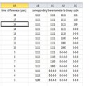
(1):time difference between two circuit will be converted to thermometer code (15bit) by such circuit and NO problem in this circuit.

(2):the thermometer code will be converted to binary code (from 15 bit to 5 bit) by thermometer to binary encoder.
i suggest the output (5 bit ) like :
if time difference is 3ps , output will be 00011
if time difference is 4ps , output will be 00100
if time difference is 5ps , output will be 00101
and so on...
my question is : what is the circuit that convert thermometer code "corresponding to the time difference" to my suggested output ?
 

You've already posted that. Why not answer the questions already asked...

Why don't you show the input code?

And

So what is it that generates the input for the thermometer to binary encoder? Do you use real hardware? Or do you use a testbench to generate bit vectors? Or (and this is the potentially problematic part) do you also simulate the fpga part that generates this 31-bit vector?
 

what is the circuit that convert thermometer code "corresponding to the time difference" to my suggested output ?
It's a priority encoder which can be e.g. implemented by the circuit shown in post #6. You have to connect the input bits in the right order.
 

You've already posted that. Why not answer the questions already asked...


And
for first question :
the input code is already shown in reply #15 (named corresponding thermometer to binary code)

for second question :
i use real hardware like :
two signal (has time difference) is applied to chain of inverters and outputs is sampled by flip flops (thermometer code)
chain of inv.jpg
 

What physically existing device is this on? I ask, because a 1 ps difference between 2 routed flip-flops sounds a bit like science fiction on all the devices I know of. Unless you do some neat trickery which somehow I am fairly confident you are not using. Because 1) you don't show the trickery I am thinking of and 2) "if you were using that, you wouldn't be asking this question".

So did you actually check that you get 1 ps of difference per consecutive flip-flop, or is that just a nice number in a spreadsheet? Because if you use the inverter chain design you just showed on real hardware ... no chance in hell you get 1 ps difference per TDC stage.

Besides, if you in fact have copy/pasted the traditional chain-O-inverters design, you must also take into account the ... wait for it ... inversions.

Also, the closer you do get to your unreachable-by-this-design target of 1 ps difference per stage ... the more you will run into another fun problem for the decoder. That problem being that while you think the pulse train will remain nice and ordered in your sampled outputs, it will in actual real hardware kind of fact, be totally out order. And 100% depending on voltage & temperature. Fun!

Sooooo if you really need 1 ps: back to the drawing board. Or more likely: adjust expectations.

PS: Not trying to be negative towards your intended design. After all, this world needs more fpga based TDC's, because they are fun. :p But I do detect a certain mismatch between what you post (1 ps time diff per flipflop stage with a straightforward chain as shown in your post) and what is actually doable in real hardware.
 
Last edited:

i,am agree with you that 1ps is more exciting :) .
to clear the image :
i use circuit known as (time amplifier) that amplify (stretch) the small time difference "that i couldn't,t measure it" to reasonable big time difference "that i can measure it" and after that i divide the output with the gain of time amplifier
example :
if two signal has like 5 psec time difference between them : this signals will applied to time amplifier (has gain 20 ). so the 5psec will be stretched to 5 psec*20=100 psec .
this 100 psec will be applied to chain of inverters and sampled output by flip flops
this scenario give my TDC an exciting resolution .
hopefully i clear the image :)
 

Status
Not open for further replies.

Part and Inventory Search

Welcome to EDABoard.com

Sponsor

Back
Top