Continue to Site

Welcome to EDAboard.com

Welcome to our site! EDAboard.com is an international Electronics Discussion Forum focused on EDA software, circuits, schematics, books, theory, papers, asic, pld, 8051, DSP, Network, RF, Analog Design, PCB, Service Manuals... and a whole lot more! To participate you need to register. Registration is free. Click here to register now.

The use of a transistor

Status
Not open for further replies.

William Levén

Newbie level 4
Newbie level 4
Joined
Feb 25, 2014
Messages
5
Helped
0
Reputation
0
Reaction score
0
Trophy points
1
Visit site
Activity points
34
hi,
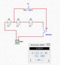
i have been working with multisim simulating a circuit-board i'm about to build but couldn't get it to work. i have been testing all parts of it now and figured out that this tiny circuit is the problem.


i want the (in this case) multimeter to get ~9v when i turn the switch on but instead i only get ~3v, im not super confident with how transistors work so please give me an explanation and explain to me how i can wire to to work properly

thanks in advance

// william
 

Re: help with use of transistor

You have the transistor collector and emitter with backwards polarity. If the polarity is corrected then the transistor is turned off but Multisim shows a small voltage by mistake.

Make it like this:
 

Attachments

  • transistor.png
    transistor.png
    9.8 KB · Views: 149
Re: help with use of transistor

You have the transistor collector and emitter with backwards polarity. If the polarity is corrected then the transistor is turned off but Multisim shows a small voltage by mistake.

Make it like this:

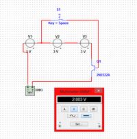
hi and thank you for your reply, i changed the polarity of the transistor and im able to turn it on and off but it still doesn't give me ~9v when i turn it on.

this is how it looks now:

- - - Updated - - -

oh sorry for my haste reply, you picture didn't load at first :)

when i wire it as you draw it up it works perfectly, but due to other functions i dont think i can wire it that way,

i have remotely controlled output from a cable that output is ~3v and i want that output to control a 9v motor.

would be most thankful if you could help me with this

//william
 

Re: help with use of transistor

Your emitter is not connected to the negative of the battery. Instead it is connected to the meter that has an extremely high resistance so an extremely low current flows. The base-emitter diode is forward-biased and its voltage drop at the extremely low current is about 0.3V from battery V1.

I changed the control of the transistor to battery V1 which is your remote control.
 

Attachments

  • transistor2.png
    transistor2.png
    14.1 KB · Views: 134
Re: help with use of transistor

The circuit shown in post 1 should work if a resistor is connected in series with the switch and a PNP transistor is used instead of the 2n2222,
 
Re: help with use of transistor

hi ive read your answers now and got it to work with a certain kind of transistor:
**broken link removed**
however i found a pair of mosfets at home and thought i might be able to use them?

the mosfets are of model IRF520
is there any way i can use them instead of the transistor in the circuit above?
 

Re: help with use of transistor

You and your horrible simulation software (Multisim?) do not understand that the base-emitter of your transistor will instantly blow up if it gets 3V because a missing resistor is needed to limit the base current as shown in my sketch in post #4. The transistor is also missing a resistor from its base to ground to turn it off. The maximum allowed current in your new transistor is only 100mA but we do not know the maximum current of your motor. The motor is missing in your simulation.

The datasheet of an IRF520 Mosfet shows that some of them barely turn on when their gate voltage is 4V but yours will be only 3V. They turn on properly with a 10V gate voltage.

ah okey thank you, i get how i should do it now

and yes its multisim, do you have any better alternatives for simulation software?

most thankful
//william
 

Re: help with use of transistor

Most of us use the free simulation software LTspice IV from Linear Technology. Its schematics are not covered with chicken pox dots.
 

Status
Not open for further replies.

Part and Inventory Search

Welcome to EDABoard.com

Sponsor

Back
Top