Continue to Site

Welcome to EDAboard.com

Welcome to our site! EDAboard.com is an international Electronics Discussion Forum focused on EDA software, circuits, schematics, books, theory, papers, asic, pld, 8051, DSP, Network, RF, Analog Design, PCB, Service Manuals... and a whole lot more! To participate you need to register. Registration is free. Click here to register now.

the transfer function ....

Status
Not open for further replies.

bharatsmile2007

Full Member level 3
Joined
Sep 19, 2007
Messages
179
Helped
1
Reputation
2
Reaction score
1
Trophy points
1,298
Activity points
2,306
hi all..

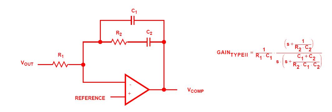
can anyone tell me how to find the transfer function of the image below..
i have the tf,but i would like to know the procedure to find it?


The problem with the shown circuit is that is has no dc feedback. That means, as a selfstanding circuit it will not work - unless it is used as part of an overall stabilizing feedback loop. Nevertheless, assuming an ideal opamp (gain infinite, offset=0) you can compute the gain (as for the classical inverting opamp circuit) as a ratio between the effective feedback impedance-to-forward impedance.
 
Status
Not open for further replies.

Part and Inventory Search

Welcome to EDABoard.com

Sponsor

Back
Top