Vermes
Advanced Member level 4

The assumption of this project was to make a cheap panel meter that allows to specify the voltage and currents flowing with the possible high accuracy at one time. Additionally, displaying the power consumption or resistance can be useful in many cases. The system consists of many popular operational amplifiers TL081, offsets of which were calibrated by multiturn potentiometers and the net of resistors. ADCs are used to measure the tension – they are available inside Atmega8 microcontroller. Measurements are displayed on LCD display 16x2 marks. The buttons on the front panel allow to switch between the current, power and load resistance indications.
The schema can be divided in two almost symmetric parts. One of them is responsible for the measurement of current and tension in negative channel of the cooperating amplifier. The second one is the same for the positive channel.
The whole description should start with the resistor R+* (0,2R), because the drop of tension in it is proportional to the current flow. The proportionality factor in this case is 1/R+*. This resistor is not present physically at the meter board, as it is a serial measuring transistor in the system of power cooperating with the meter. Point A should be connected to the higher potential (before the resistor in power supply), and point B should be connected to the lower potential (after the meter resistor). The operational amplifier U3 (TL081) compares tension in point B to the tension in resistors R1-R4 (200R) relative to point B. Its output controls the transistor T1 (BC857), so the drop of tension on parallel connection of R1-R4 is equal with the drop on measuring resistor R+*. Parallel connection of R1-R4 is used instead of a single resistor in order to improve the tolerance of resistance and the accuracy. The current flow through T1 and R1-R4, also flows through the resistors R5-R8 (9,1k). The value of there resistors (9,1k/4=2,27k) is 45,5 times greater than the parallel connection of R1-R4 (50R), so the voltage across the capacitor C8 (100nF) is 45,5 times greater than the measuring resistor R+*. Current measurement can be done in up to 4 measuring ranges implemented by resistors R9-R12 (2,4k), R13-R16 (750k) and N-MOSFETs with a complementary pair T3-T4. (IRF7106/IRF7105). Elements T3 and T4 contain two transistors of opposite polarities in one housing. If, for example, N-MOSFET of T3 and T4 would conduct (high state on G1 gates), the current flowing through T1 would hit on all the parallel connections of resistors R5-R16, realizing the lowest voltage multiplier and the biggest measurement range.
The tension from resistive divider filtered by C8 gets on the non-diverse buffer input U4 (TL081) and through the resistor R21 (9,1k) to the input of analog-digital converter via GP1 connector (HEADER). The transistors changing the range are controlled by microcontroller via GP2 connector (HEADER). The voltage at the buffer output U4 shouldn't exceed 2,56V, because the converter ADC cooperates with the reference voltage. When the voltage comes close to his value, the current range is changed automatically to the larger one.
Resistors R17-R20 (47k) and multiturn potentiometers P1-P2 (10k) allow to level the offset of the amplifiers U3 and U4. In first phase of starting the system, they shouldn't be mounted. Condensers C7 (100nF), C9-C10 (100nF) filter the voltages that power the amplifiers U3 and U4. U3 amplifier runs on positive power supply at max 36V, while U4 runs on symmetric power supply +/- 5V to move signals near the ground. The above description applies to the current measurement of the positive supply rail.
The measurement of current on negative supply rail is very similar. The measuring resistor is R-* (0,2R), point C is to be connected to lower potential, and point D to the higher. Thanks to the operational U6 (TL081) and transistor T2 (BC847), the drop of tension on parallel connection R41-R44 (200R) is of the same value as in the measuring resistor R-*. The current through R41-R44 and T2 also flows through parallel connection R23-R25 (9,1k) and R34 (9,1k). During work of the system on diverse input of the amplifier U5 (TL081) the mass potential would determine, so the resistor R34 is connected parallel to R23-R25. The tension on filtering condenser C13 (100nF) is 45,5 times greater than the voltage on measuring resistor R-*. The amplifier U1 runs in diverse configuration at reinforcement of -1, what is crucial to make the analog-digital converter in the microcontroller possible, because it works only at positive voltages. Similar to the positive channel, thanks to MOSFET-P from T3 and T4 and the resistor R26-R29 (2,4k) and R30-R33 (750R), changing the ranges of current measure is possible. The gates of P-MOSFET transistors need negative control relative to the mass, so they were connected to the microcontroller through optocouplers OPT1-OPT2 (LVT357T), which allow to control the gates of transistors by positive tension relative to the mass. Resistors R80-R81 (10k) pull up the gates to the mass potential when OPT1 and OPT2 are off and R45-R46 (1k) limit the current of optocouples diodes. The output of diverse buffer U5 goes to the resistor R38 (9,1k) and further to the connector GP1.
The resistors R36-R37 (47k), R39-R40 (47k) and potentiometers P3 (10k) and P4 (10k) allow to level the amplifiers U5 and U6 offset. Condensers C11-C12 (100nF) and C14 (100nF) filter the power voltage of operational amplifiers.
The measurement of voltage is done in a less complicated way and works on base of voltage divider. In positive channel there is a divider consisted of parallel connection R58-R61 (560k) and R50-R53 (160k). Degree of division is 10/45. The tension from the divider is filtered with C15 capacity (100nF). After that it goes to the buffer U7 (TL081) and through the resistor R49 (9,1k) to the output connector GP1, which ensure the contact with microcontroller. The measurement of the voltage is done in two ranges changed by N-MOSFET transistor from a complementary couple T5 (IRF7105/IRF7106). When the transistor leads to the resistors R50-R53, R54-R57 (44,2k) join parallel, changing the degree distribution of the divider.
The measurement of negative values is done in a similar way. The divider consists of resistors R70-R73 (560k) and R63-R65 (160k). Like in negative range for the current, resistor R74 (160k) is connected parallel to resistors R63-R65. Condenser C18 (100nF) filters the tension from the divider, which is reversed by amplifier U8 (TL081). The ratio of resistors R75 (160k) and R74 (160k) determine the strengthen U8 on -1 level. Changing of the voltage measurement range on the negative runs thanks to P-MOSFET transistor from the couple T5 and resistors R66-R69 (44,2k), identical as in positive. To control P-MOSFET optocouple OPT3 (LTV357) and resistors R82 (10k) and R79 (1k) are used.
Resistors R47-R48 (47k), R76-R77 (47k) and potentiometers P5-P6 (10k) allow to zero the amplifiers' U7 and U8 offset. Condensers C16-C17 (100nF) and C19-C20 (100nF) filter the supply voltage of the amplifiers. Diodes D1-D4 (BAT85) secure against excessive increase of voltage on operational amplifiers U4, U5, U7 and U8 inputs. Any other silicon diode in SOD80 housing can be used instead of them, when it turns out that the operational amplifiers do not work reliably (tests showed that it depends on the producer of amplifiers).
The main element of the system is microcontroller U1 (Atmega8) with quartz resonator X1 (16MHz) and condensers C1 (22pF) and C2 (22pF). The measurement is done by analog-digital converters in-built in the microcontroller. The ADC can run on internal or external reference voltage of 2,56V. As an external reference circuit, regulated Zener diode U2 (TL431) with cooperating elements P2 (10k), R2 (470R) and C5 (100nF) are used. Condensers C5 (100nF) and C15 (10uF) filter the reference voltage and the potentiometer P2 allows to tune the voltage level.
The inputs of converters are filtered by condensers C6-C9 (100nF), which make filter RC together with serial output resistor, that is in analog part of the circuit. Connectors GP1 and GP2 ensure the contact between the plates.
Condensers C4 (100nF) and C14 (10uF) and suppressor L1 (10uH) filter the voltage that powers the converter. Condenser C3 (100nF) close to the microcontroller ensures filtering the voltage that powers the digital part of the microcontroller. Because the meter would be used in power supply and powered by auxiliary transformer's winding, there is also a stabilized power supply with rectifier bridge Br1 (1A) on the plate. Condensers C10 (220uF), C11 (100nF), C12 (100nF) and C13 (47uF) cooperate with the stabilizer U3 (7805).
Presentation of measurements is made by display W1 (16x2). Its contrast can be tuned with potentiometer P1 (10k). The current of lighting is limited by resistor R1 (47R). Buttons S1-S2 (uSwitch) allow to change the mode of meter and diodes D1 and D2 signal exceeding the highest current measurement range. Diodes' currents are limited by resistors R3-R4 (470R).
Connecting the meter to the symmetric power supply:
Points highlighted in the system – initial start:
When the analog part of the meter is connected to the power supply, first start can be made. All control inputs G1-G6 should be shorted to the ground. After activating the power supply, you have to ensure if stabilizers U1 and U2 give the appropriate voltage (+/-5V). Then, the measurement in few key points of the system can be made. The voltage between points A and B is proportional to flowing current and should be equal with the voltage between points A and E. It means that the measure system cooperates properly with amplifier U3. Little differences of voltage like 1mV are tolerated, because the offsets hadn't been zeroed yet. The voltage in point F of the mass should be about 45,5 times greater then between points A and E (control signals are shorted to the ground, so the system runs with the highest strengthen). A similar measurement can be made on the opposite side of the power supply rail. The voltage between C and D should be equal with the voltage between points C and G. In point H there should be voltage 45,5 times greater of the mass (absolute value) than between C and G.
Next, working of voltage buffers U4 and U5 can be checked. The voltage in point Ucurr+ at the output connector should be equal with the voltage in point F (of the ground). The voltage in point Ucurr- should be equal with the voltage in point H (with '-' mark).
Also, you can check the voltages in points F and H for other degrees of the divider. The choice is made by changing logic levels of control signals G1-G4.
The last part worth checking are dividers of voltages measurement. The voltage in point I of the ground should be 4,5 times smaller than the voltage in point B. On U+ output, the voltage should be equal with the voltage in point I. On the opposite side of the power supply rail, the situation should be similar. The voltage in point J should be 4,5 times smaller than in point D (absolute value). In point U-, the voltage should be the same as in point J, with the opposite mark.
Also, you can check the second level of divide, giving the high state (5V) on control signals G5 and G6.
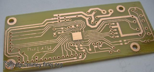
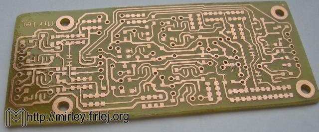
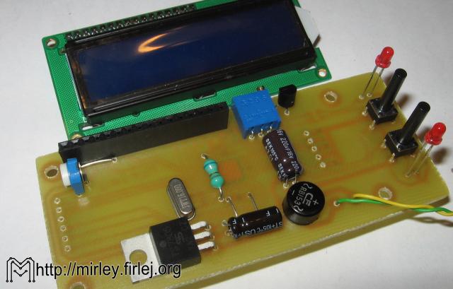
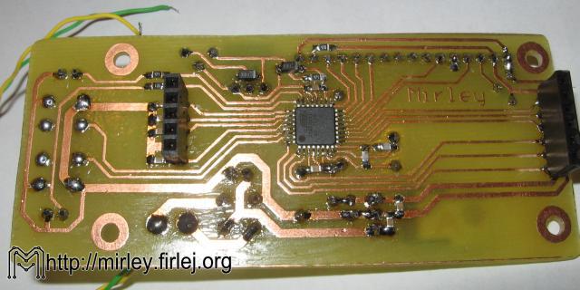
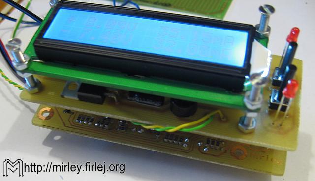
Photos:

Link to original thread – Miernik panelowy do zasilacza symetrycznego