Continue to Site

Welcome to EDAboard.com

Welcome to our site! EDAboard.com is an international Electronics Discussion Forum focused on EDA software, circuits, schematics, books, theory, papers, asic, pld, 8051, DSP, Network, RF, Analog Design, PCB, Service Manuals... and a whole lot more! To participate you need to register. Registration is free. Click here to register now.

The Metal Plate Behind Antenna Increases Gain??

Status
Not open for further replies.

denizduran

Member level 2
Joined
Sep 14, 2021
Messages
48
Helped
0
Reputation
0
Reaction score
1
Trophy points
8
Activity points
463
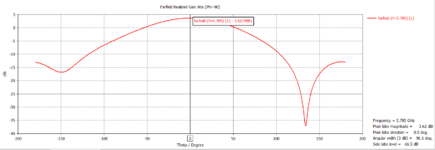
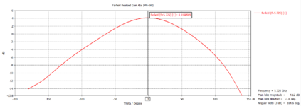
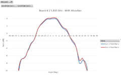
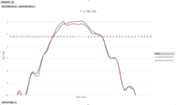
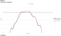
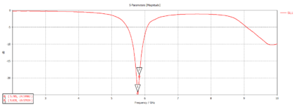
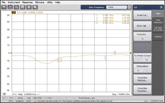
I have a simple 5 GHz patch antenna in my hand. When I add the metal back plate that is going to help mount the antenna to the radio into my simulations, the gain increases noticeably. I have attached the gain and return loss results for just the patch simulated alone and when simulated including the metal back plate. Can anyone help me understand what's going on? I also measured the metal back plate + antenna in the anechoic chamber and the results do not match with the simulations, there is no such gain increase with the metal back plate. I have also attached the anechoic chamber measurements.

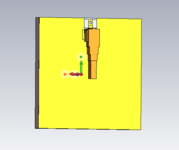
First file: patch antenna simulation
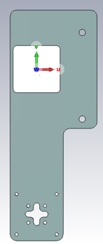
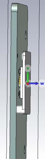
Second file: patch antenna + metallic back plate simulation
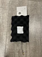
Third File: patch antenna + metallic back plate anechoic chamber radiation pattern measurement

Please help!
 

Attachments

  • f = 5.785 GHz.PNG
    f = 5.785 GHz.PNG
    28.4 KB · Views: 115
  • f = 5.725 GHz.PNG
    f = 5.725 GHz.PNG
    28.6 KB · Views: 121
  • Anechoic_Chamber_Results.PNG
    Anechoic_Chamber_Results.PNG
    33.5 KB · Views: 146

When the microstrip transmission line was invented in 1952, was an issue proposing this line, because at some extent this type of transmission line would radiates due to the friging fields that appear at the edges, between the top metal and the ground metal, through the substrate material.
The patch antenna can be viewed as an open circuited microstrip transmission line, which design is doing everything as possible to increase the fringing fields and so, to increase the radiation field.
If is no ground plane, there are no fringing fields to radiate, and the only radiation is from the metal patch itself, which is not so much.
 

We are talking about 0.5dB more gain with the extra ground, correct?

A photo would help a lot to understand what we are discussing here.

I guess the device is patch antenna (patch + ground) with/without an additional metal plate. From the post it is not clear at what distance behind the patch antenna ground that additional metal plate is located.

Also, it is not clear how large the ground plane of the patch itself is (without the additional metal plate). From diagrams there is some backside radiation, so the extra gain of 0.5dB with an additional (larger) ground looks possible to me.
True, we are talking about half a dB of gain increase - or more - at different frequencies, I have attached the front and back view of the antenna and the metallic back plate. I am also attaching the CST file because in case you would be kind enough to take a look at it.

Another thing is that when I add the radome to the antenna ( 1 mm distance from the antenna and it's thickness is 2 mm) I don't get a significant gain degradation (around half a dB decrease in gain) in simulation but when I measure it in the anechoic chamber I loose 2 dB gain at 5.785 GHz and the antenna has a max gain of 4dB so a 2dB gain loss is so much. At 5.835 GHz I nearly have 0 gain even though this antenna is designed to work at those two frequencies...

I have also attached the anechoic chamber radiation pattern results when the antenna is mounted with the radome and the metallic back plate to the chamber where you can see the gain dropping immensely. I also added absorbers to the peripherals of the antenna to reduce radiation pattern distortion while testing it in the chamber.

File 1 = Front view of antenna
File 2 = Back view of antenna
File 3 = The antenna covered by a radome and supported by a metallic back plate
File 4 = "" side view
File 5 = A picture of the real structure that was put to test in the chamber
File 6 = Result of radiation pattern gain at 5.785 GHz from the chamber (Gain drops from 4 dBi to 2 dBi)
File 7 = Result of radiation pattern gain at 5.835 GHz from the chamber (Gain drops from 4 dBi to 0.3 dBi)
File 8 = CST zip file that includes the metallic back plate, radome and the antenna
 

Attachments

  • Front_Plane.PNG
    Front_Plane.PNG
    4.6 KB · Views: 94
  • Back_Plane.PNG
    Back_Plane.PNG
    12.3 KB · Views: 102
  • Antenna+radome+plate.PNG
    Antenna+radome+plate.PNG
    9.2 KB · Views: 110
  • Antenna+radome+plate2.PNG
    Antenna+radome+plate2.PNG
    14.4 KB · Views: 95
  • IMG_8784.jpg
    IMG_8784.jpg
    5.2 MB · Views: 103
  • Board 4 Anechoic Chamber Result - 5.785 GHz.PNG
    Board 4 Anechoic Chamber Result - 5.785 GHz.PNG
    33 KB · Views: 96
  • Board 4 Anechoic Chamber Result - 5.835GHz.PNG
    Board 4 Anechoic Chamber Result - 5.835GHz.PNG
    28.4 KB · Views: 103
  • patch_antenna.zip
    4.3 MB · Views: 100

I can't check your CST model because I use another 3D EM solver (Empire XPU).

The small effect that you see in simulation from 2mm radome surprises me, I would expect larger effect due to de-tuning if your radome is made from a solid plastic material. What material is that?
Does the shift in resonance frequency agree between simulation and measurement? Do you surely use correct radome material properties?
The material is Hei Cast 8150 (dielectric = 3.7 & loss factor = 0.035) which is an alternative material for Polylac in both simulation and in real life.

I checked how plane waves react to this material by using a horn antenna and it showed a decrease of 0.5 dB as well when the radome is put infront of the horn in a 1mm distance. The problem is I am loosing way to much gain in chamber measurements, I really am desperate to find what the problem is..
 

I checked how plane waves react to this material by using a horn antenna and it showed a decrease of 0.5 dB as well when the radome is put infront of the horn in a 1mm distance.

I don't think this test is valid/applicable for the patch antenna case. For the horn you are already in the plane wave region, but for the patch yopu are in the extreme near field. I would really check S11, expecting heavy resonance shift of the patch.
 

I would really check S11, expecting heavy resonance shift of the patch.
File 1: CST simulation S11 graph
File 2: Keysight VNA S11 graph

Yes, the resonant frequency has shifted to the left!! But what does that have to do with the radome decreasing the gain?
 

Attachments

  • Return_Loss.PNG
    Return_Loss.PNG
    21.3 KB · Views: 91
  • Board_4.png
    Board_4.png
    75.2 KB · Views: 92

There are different definitions of antenna gain, including or excluding mismatch loss.

The gain that you measure is reduced by mismatch. High reflection = less transmitted signal = lower measured gain.

Gain definition in EM software often excludes mismatch loss by default. In my EM solver the wording is "gain" and "realized gain". Only "realized gain" shows the extra loss from mismatch that we see in real life measurement.
 

I don't think this test is valid/applicable for the patch antenna case. For the horn you are already in the plane wave region, but for the patch yopu are in the extreme near field. I would really check S11, expecting heavy resonance shift of the patch.
Also, may I ask, how is it that when the horn is radiating, 1 mm is considered the far-field and the patch very near field?
 

The origin of radiation is deep inside the horn, and you have almost plane waves near the front of the horn.

That is very different from the fields a few mm away from the patch, believe me or not. I recently did studies of patch antenna near field for a customer and it is really inhomogenous at that distance.
 
Aaa I understand, makes soo much sense!! Please do share any other interesting explanations you have in this topic!
 

Status
Not open for further replies.

Part and Inventory Search

Welcome to EDABoard.com

Sponsor

Back
Top