Continue to Site

Welcome to EDAboard.com

Welcome to our site! EDAboard.com is an international Electronics Discussion Forum focused on EDA software, circuits, schematics, books, theory, papers, asic, pld, 8051, DSP, Network, RF, Analog Design, PCB, Service Manuals... and a whole lot more! To participate you need to register. Registration is free. Click here to register now.

The Kill A Watt LCD driver

Status
Not open for further replies.

evios

Junior Member level 1
Joined
Nov 26, 2008
Messages
15
Helped
0
Reputation
0
Reaction score
0
Trophy points
1,281
Activity points
1,420
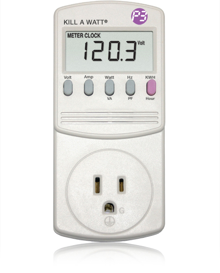
kill a watt serial interface

Hi all the experts here:

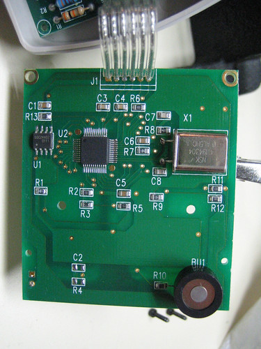
Basically I was having my project. But then I need the data from a device called Kill A Watt. Before it has been drived to the output, there are 6 connections to the LCD driver as shown below:
3061805595_8cb0eaa264.jpg


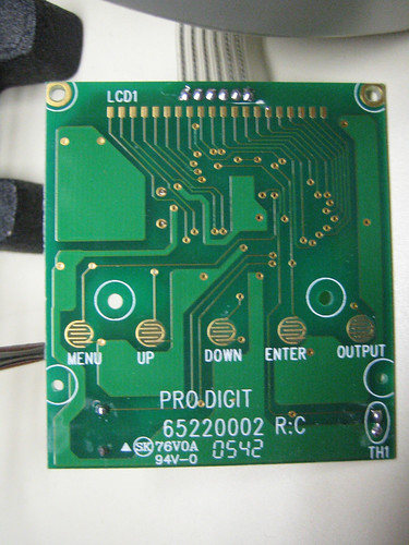
The LCD seems to have 20 pins configuration:
3061805971_3eddf5c317.jpg


Can anyone advice me for that? Because I really need it for the project. Thanks.

Any references are welcomed too.

Thanks
 

1-wire kill a watt

Some LCD has serial interface that's why you have 6 wire ribbon cable, 20 pins it is COG(chip on glass) display, so your PCB can drive two different types of the display
 

lcd driver 6 wire

If it is a standard alphanumeric display you need 6 wires to use in 4 bit mode. Cannot really tell from your photos whether Alpha or Graphic.

You need
D4-D7 4 wires
E 1 Wire
RS 1 Wire

Connect WR to ground (write mode)

Power of course
And I think CON connects to ground for darkest display, really needs around 10k pot across power, with centre to CON

Not sure of connections if its a graphic display.
 

configure kill a watt

Thanks for the replies!!!
But what is meant by these pins anyway?
D4-D7
E 1
RS 1

Sorry I just found it a bit complicated. Thanks again.
 

kill a watt setup

D4-D7 are data lines Leave D0-D3 unconnected
E = Display Enable
RS = Display Reset
As you are probably only writing to the display, you should connect W/R to 0V
Apart from power and contrast, these 6 lines are all the data connections you need for 4bit operation. Always assuming that this is an Alphanumeric display, and your software is setup to operate in 4 bit mode. If this is a graphics display, the the above will not apply, there are different sorts.
 

lcd graphics display chip on ribbon cable

Well thanks for the reply...
main_p4400.jpg


I think this is more like Alphanumeric display.
I just want to get the reading out and input into PIC
 

This is a custom display, just for this meter. What I have said before is not relevant to this.
Sorry no idea how you would extract data from this unit. Its my guess that the display is a serial device.
 

Status
Not open for further replies.

Part and Inventory Search

Welcome to EDABoard.com

Sponsor

Back
Top