Continue to Site

Welcome to EDAboard.com

Welcome to our site! EDAboard.com is an international Electronics Discussion Forum focused on EDA software, circuits, schematics, books, theory, papers, asic, pld, 8051, DSP, Network, RF, Analog Design, PCB, Service Manuals... and a whole lot more! To participate you need to register. Registration is free. Click here to register now.

TFT LCD with TOUCH , ETHERNET , microSD

Status
Not open for further replies.

abolfazlk873

Junior Member level 3
Joined
Dec 2, 2012
Messages
25
Helped
0
Reputation
0
Reaction score
0
Trophy points
1,281
Activity points
1,488
hi,
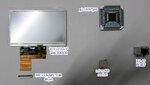
We are trying to interface a 4.3" tft lcd module with touch panel , microSD and Ethernet to a pic micro-controller. the micro-controller is pic18f97j60 and the LCD driver is SSD1963. We are designed that, but i want to display my pcb project to you for debugging that.
Industrial Design is my target.
In this file is schematic and pcb.
View attachment tft lcd.rar
I was Considered 4 pads( 3 millimeters ) for keeping the LCD on the board . Is that true.
Friends do not hesitate your views.
 
Last edited:

What program do the schematic and pcb come from?
 

Hi pwdixon ,
My software is Altium Designer 09.
 

That'll be why I can't open the files then, I can't afford Altium.
Hi pwdixon ,
this is new file . that's format is *.pdf . I hope that is not a problem.
 

Attachments

  • tft lcd2.rar
    933.5 KB · Views: 112

I can see the files now thanks.
Couldn't see P7 which I assume should connect to the lcd or the lcd on the pcb layout so I can't comment on mounting the LCD. Also, I would need to know the LCD type to comment on mounting.

Edited:
I found P7 an FPC connector but that doesn't help to comment on LCD mounting.

Hi pwdixon ,
Yes the P7 is the FPC connector that is found on the bottom of pcb.
in this file is the datasheet of lcd , driver of lcd ssd1963 and the picture of lcd.
 

Attachments

  • LCD.rar
    1.2 MB · Views: 98
  • PICTURE1.jpg
    PICTURE1.jpg
    192.1 KB · Views: 90
Last edited:

I can't see how you are thinking that you are going to use 4 pads to hold the display on the board, often these types of display are double-sided taped to the board, of course that requires that there is adequate empty space (no components) on the board for the LCD.

On separate note, I've not seen an LCD connected like this before, the LCD datasheet says it has a controller built-in and yet you appear to have one on your board too, what's that about?

Hi pwdixon ,
Yes your viewpoint is right. Mention a few things to know:
1- I didn't work with the tft-lcd therefore I don't know what do i do Exactly ?
2- In datasheet , I've encountered this issue that the lcd module has a one driver HX8257A-01 but the seller said me which one driver externally required.
Thank you if you help me about to install LCD on the Board.
 

I dont really understand is the controller on the LCD or on the board because it looks like you have both?
How are you driving the LCD in software? At the very least the two controllers mentioned will probably need different initialisation routines.
 

Status
Not open for further replies.

Part and Inventory Search

Welcome to EDABoard.com

Sponsor

Back
Top