Continue to Site

Welcome to EDAboard.com

Welcome to our site! EDAboard.com is an international Electronics Discussion Forum focused on EDA software, circuits, schematics, books, theory, papers, asic, pld, 8051, DSP, Network, RF, Analog Design, PCB, Service Manuals... and a whole lot more! To participate you need to register. Registration is free. Click here to register now.

Testing a High input impedance amplifier

Status
Not open for further replies.

mateusbatera

Member level 2
Joined
Nov 30, 2010
Messages
42
Helped
3
Reputation
6
Reaction score
3
Trophy points
1,288
Activity points
1,606
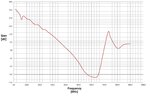
I'm trying to measure the gain of a high input impedance amplifier to use with a nelectrically small receiving antenna. I made some measurements using a signal generator in the input and a spectrum analyzer in the output. As a result, I got the figure attached. It's weird, because the gain rolls of until 640MHz, and then it starts rising again.

Is my measurement setup correct? I was wondering if the problem is that this amplifier is supposed to be used with an antenna in the input. Maybe my 50ohm signal generator does not model an small antenna correctly.
 

Attachments

  • Gain.jpg
    Gain.jpg
    230.7 KB · Views: 107

You didn't show the amplifier circuit, so we can hardly guess about the reason for the shown frequency characteristic. Measuring with a 50 ohm generator impedance isn't bad at all and should give a realistic view of the amplifier behaviour. An electrically small antenna can be expected to have a mostly capacitive impedance most likely won't behave anything better with the amplifier.

Are you sure, that the amplifier circuit is really suited for the intended wide band operation? For an exact simulation, you would want to determine the antenna and amplifier impedance with a network analyzer and calculate the resulting gain.
 

Your 50 ohm generator will only give a constant output when it is driving a 50 ohm cable terminated in a 50 ohm load. If the cable is operating into a high impedance then there will be reflections on it with the first "null" when the cable length is a quarter of a wavelength long. Followed by a X 2 peak when the cable is 1/2 wavelength long.
Frank
 

Your 50 ohm generator will only give a constant output when it is driving a 50 ohm cable terminated in a 50 ohm load.
An industry standard RF generator will expose 50 ohm output impedance and produce a fairly constant output voltage when connected through a 50 ohm cable to a high impedance load as well.
 

The level (EMF) behind the signal generators output impedance may remain constant but the energy travelling down the line cannot be absorbed so it is reflected. As it has travelled a total distance of 1/2 wavelength it is anti phase with the originating voltage so causes a cancellation, so the energy delivered to the load falls. See :- Standing wave ratio - Wikipedia, the free encyclopedia
VSWR is the "Voltage standing wave ratio", i.e. the ratio of the maximum voltage on a line to the minimum. the max and min are caused by the originating voltage being +- the reflected voltage (by a miss terminated line).
Frank
 

I was particularly talking about the voltage delivered to the load, not about reflection factor, VSWR or similar stuff. And emphasizing the simple fact, that the generator can give a constant (= frequency indpendent) output voltage, although the load isn't matched. In my view, Output voltage obiously refers to the observable voltage at the load.

Of course, open end implies a reflection factor of +1 and thus VSWR of infinity. But as long as the cable is matched at the source side, no further reflections will occur. The voltage at the cable end will be twice the value delivered to a 50 ohm loaded case, but still frequency independent. A high impedance amplifier connected to the cable end doesn't notice the VSWR, you get a flat frequency response, respectively an undistorted pulse transmission in time domain.
 
  • Like
Reactions: WimRFP

    WimRFP

    Points: 2
    Helpful Answer Positive Rating
Chuckey: I agree with FVM, a 50 Ohms source with a 50 Ohms cable, shows a 50 Ohm source impedance to the load. In other words the load doesn't see any difference between direct connection to the generator or connection via the coaxial cable (except for some loss and some time delay). Due to the internal attenuator, RF generators for measurement show impedance close to the specified value (mostly 50 Ohms). In case of Power Amplifiers, the situation can be completely different.

Mateusbatera: To give any useful feedback, you should post the circuit. To be sure, you may verify correct operation of your cables and generator (with the spectrum analyzer).

Your 50 ohms source definitely doesn't model the small electrical antenna. If the input impedance of the amplifier is really far above 50 Ohms, your setup at least gives the voltage gain of the amplifier.

To model the antenna, best is to determine the capacitance (via measurement, empirical formulas or EM simulation) and put this capacitance in series with your amplifier (between the coaxial cable and your circuit not between the generator and the cable).

Re(Zant) for the real whip antenna will probably be far below 50 Ohms (for a very short whip < 0.1 lambda), but as a first start, you can just use the generator with the capacitor.

Next step may be modelling Re(Zant) better as Re(Zant) may affect stability of the circuit.
 
  • Like
Reactions: FvM

    FvM

    Points: 2
    Helpful Answer Positive Rating
Status
Not open for further replies.

Part and Inventory Search

Welcome to EDABoard.com

Sponsor

Back
Top