ChaXi
Junior Member level 1
Hello to everybody!
I'm new on programming FPGA and i have a question about a problem i can't resolve when i'm testbenching my component:
The project is a driver for the LCD installed on the evaluation board;
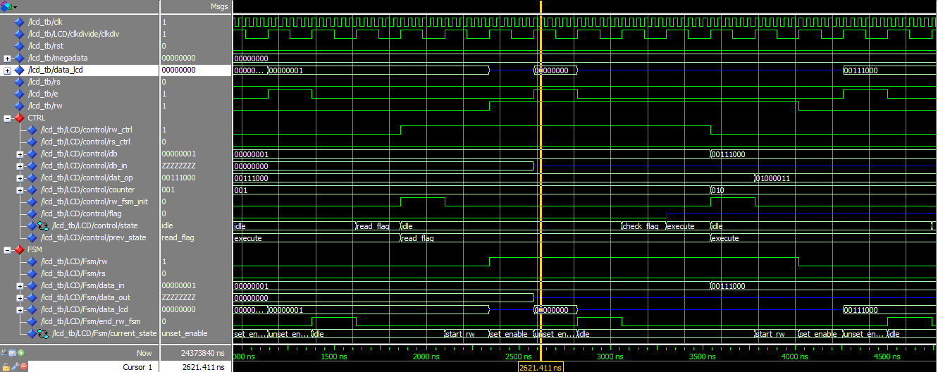
below there is the part of the code that got me problems and in particular it is on the signal data_lcd (declared as inout). When i simulate data reading from lcd (assigned from testbench) i have a conflict and the signal become red... i read that it is because the port is driven by two different part so i added in testbench lines 98 to 108 to put my signal to all 'Z' when i'm not reading... but it seems it doesn't work... i post also an image of my wave: when it get red there should be all '0' simulating the reading from external lcd but...
any suggestion on how to solve problem?
thanks in advance..
[INDENT][I]----------------------------------------------------------------------------------
library IEEE;
use IEEE.STD_LOGIC_1164.ALL;
use IEEE.NUMERIC_STD.ALL;
-- Uncomment the following library declaration if instantiating
-- any Xilinx primitives in this code.
--library UNISIM;
--use UNISIM.VComponents.all;
entity rw_fsm is
Port ( rst : in STD_LOGIC; -- reset asincrono
rw : out STD_LOGIC; -- read or write to lcd
rs : out STD_LOGIC; -- register select to lcd
clk : in STD_LOGIC;
start : in STD_LOGIC;
data_in : in STD_LOGIC_VECTOR (7 downto 0); -- data from display_ctrl
data_out : out STD_LOGIC_VECTOR (7 downto 0); -- data to display_ctrl when reading busy flag
data_lcd : inout STD_LOGIC_VECTOR (7 downto 0); -- data interfacing between ldc and display
e : out STD_LOGIC; -- signal enable to lcd
rw_in : in STD_LOGIC; -- read or write from display ctrl
rs_in : in STD_LOGIC; -- rs from display ctrl
end_rw_fsm : out STD_LOGIC); -- feedback to lcd display
end rw_fsm;
architecture state_machine of rw_fsm is
type Statetype is (idle, start_rw, set_enable, unset_enable);
signal current_state : Statetype;
begin
state_decision: process(rst, clk) begin
if (rst = '1') then
current_state <= idle; -- reset asincrono
data_lcd <= "00000000";
rw <= '0';
rs <= '0';
data_out <= "00000000";
e <= '0';
end_rw_fsm <= '1';
elsif rising_edge(clk) then
case current_state is
when idle =>
end_rw_fsm <= '0';
if start = '1' then
current_state <= start_rw;
--end_rw_fsm <= '0';
elsif start = '0' then
current_state <= idle;
end if;
when start_rw =>
rw <= rw_in;
rs <= rs_in;
current_state <= set_enable;
when set_enable => -- understanding if reading or writing and preparing data
e <= '1';
if rw_in = '0' then
data_lcd <= data_in;
elsif rw_in = '1' then
data_lcd <= (others => 'Z');
data_out <= data_lcd;
end if;
current_state <= unset_enable;
when unset_enable =>
e <= '0';
end_rw_fsm <= '1';
current_state <= idle;
end case;
end if;
end process state_decision;
end state_machine;[/I]
[/INDENT]
The follow is my TestBench:[INDENT][I]--------------------------------------------------------------------------------
LIBRARY ieee;
USE ieee.std_logic_1164.ALL;
-- Uncomment the following library declaration if using
-- arithmetic functions with Signed or Unsigned values
--USE ieee.numeric_std.ALL;
ENTITY lcd_tb IS
END lcd_tb;
ARCHITECTURE behavior OF lcd_tb IS
-- Component Declaration for the Unit Under Test (UUT)
COMPONENT lcdstruct
PORT(
clk : IN std_logic;
rst : IN std_logic;
rs : OUT std_logic;
e : OUT std_logic;
rw : OUT std_logic;
data_lcd : INOUT std_logic_vector(7 downto 0)
);
END COMPONENT;
--Inputs
signal clk : std_logic := '0';
signal rst : std_logic := '0';
signal megadata : std_logic_vector(7 downto 0);
--BiDirs
signal data_lcd : std_logic_vector(7 downto 0);
--Outputs
signal rs : std_logic;
signal e : std_logic;
signal rw : std_logic;
-- Clock period definitions
constant clk_period : time := 40 ns;
BEGIN
-- LCDcomponent
LCD: lcdstruct PORT MAP (
clk => clk,
rst => rst,
rs => rs,
e => e,
rw => rw,
data_lcd => data_lcd
);
-- Clock process definitions
clk_process :process
begin
clk <= '0';
wait for clk_period/2;
clk <= '1';
wait for clk_period/2;
end process;
--Stimulus process
stim_proc : process(e,rw)
begin
if rising_edge(e) and rw = '1' then
data_lcd <= megadata;
else
data_lcd <= (others => 'Z');
end if;
end process stim_proc;
megadata <= "00000000";
--wait for clk_period*25/2;
--megadata <= "11111111";
-- wait for clk_period*8;
-- megadata <= "00110101";
-- Reset process
rst_proc: process
begin
rst <= '1';-- hold reset state for 100 ns.
wait for clk_period*2;
rst <= '0';
wait;
end process;
END;
[/I][/INDENT]
[IMG][url=https://obrazki.elektroda.pl/35_1306144291.jpg][img]https://obrazki.elektroda.pl/35_1306144291_thumb.jpg[/url][/IMG]
I'm new on programming FPGA and i have a question about a problem i can't resolve when i'm testbenching my component:
The project is a driver for the LCD installed on the evaluation board;
below there is the part of the code that got me problems and in particular it is on the signal data_lcd (declared as inout). When i simulate data reading from lcd (assigned from testbench) i have a conflict and the signal become red... i read that it is because the port is driven by two different part so i added in testbench lines 98 to 108 to put my signal to all 'Z' when i'm not reading... but it seems it doesn't work... i post also an image of my wave: when it get red there should be all '0' simulating the reading from external lcd but...
any suggestion on how to solve problem?
thanks in advance..
[INDENT][I]----------------------------------------------------------------------------------
library IEEE;
use IEEE.STD_LOGIC_1164.ALL;
use IEEE.NUMERIC_STD.ALL;
-- Uncomment the following library declaration if instantiating
-- any Xilinx primitives in this code.
--library UNISIM;
--use UNISIM.VComponents.all;
entity rw_fsm is
Port ( rst : in STD_LOGIC; -- reset asincrono
rw : out STD_LOGIC; -- read or write to lcd
rs : out STD_LOGIC; -- register select to lcd
clk : in STD_LOGIC;
start : in STD_LOGIC;
data_in : in STD_LOGIC_VECTOR (7 downto 0); -- data from display_ctrl
data_out : out STD_LOGIC_VECTOR (7 downto 0); -- data to display_ctrl when reading busy flag
data_lcd : inout STD_LOGIC_VECTOR (7 downto 0); -- data interfacing between ldc and display
e : out STD_LOGIC; -- signal enable to lcd
rw_in : in STD_LOGIC; -- read or write from display ctrl
rs_in : in STD_LOGIC; -- rs from display ctrl
end_rw_fsm : out STD_LOGIC); -- feedback to lcd display
end rw_fsm;
architecture state_machine of rw_fsm is
type Statetype is (idle, start_rw, set_enable, unset_enable);
signal current_state : Statetype;
begin
state_decision: process(rst, clk) begin
if (rst = '1') then
current_state <= idle; -- reset asincrono
data_lcd <= "00000000";
rw <= '0';
rs <= '0';
data_out <= "00000000";
e <= '0';
end_rw_fsm <= '1';
elsif rising_edge(clk) then
case current_state is
when idle =>
end_rw_fsm <= '0';
if start = '1' then
current_state <= start_rw;
--end_rw_fsm <= '0';
elsif start = '0' then
current_state <= idle;
end if;
when start_rw =>
rw <= rw_in;
rs <= rs_in;
current_state <= set_enable;
when set_enable => -- understanding if reading or writing and preparing data
e <= '1';
if rw_in = '0' then
data_lcd <= data_in;
elsif rw_in = '1' then
data_lcd <= (others => 'Z');
data_out <= data_lcd;
end if;
current_state <= unset_enable;
when unset_enable =>
e <= '0';
end_rw_fsm <= '1';
current_state <= idle;
end case;
end if;
end process state_decision;
end state_machine;[/I]
[/INDENT]
The follow is my TestBench:[INDENT][I]--------------------------------------------------------------------------------
LIBRARY ieee;
USE ieee.std_logic_1164.ALL;
-- Uncomment the following library declaration if using
-- arithmetic functions with Signed or Unsigned values
--USE ieee.numeric_std.ALL;
ENTITY lcd_tb IS
END lcd_tb;
ARCHITECTURE behavior OF lcd_tb IS
-- Component Declaration for the Unit Under Test (UUT)
COMPONENT lcdstruct
PORT(
clk : IN std_logic;
rst : IN std_logic;
rs : OUT std_logic;
e : OUT std_logic;
rw : OUT std_logic;
data_lcd : INOUT std_logic_vector(7 downto 0)
);
END COMPONENT;
--Inputs
signal clk : std_logic := '0';
signal rst : std_logic := '0';
signal megadata : std_logic_vector(7 downto 0);
--BiDirs
signal data_lcd : std_logic_vector(7 downto 0);
--Outputs
signal rs : std_logic;
signal e : std_logic;
signal rw : std_logic;
-- Clock period definitions
constant clk_period : time := 40 ns;
BEGIN
-- LCDcomponent
LCD: lcdstruct PORT MAP (
clk => clk,
rst => rst,
rs => rs,
e => e,
rw => rw,
data_lcd => data_lcd
);
-- Clock process definitions
clk_process :process
begin
clk <= '0';
wait for clk_period/2;
clk <= '1';
wait for clk_period/2;
end process;
--Stimulus process
stim_proc : process(e,rw)
begin
if rising_edge(e) and rw = '1' then
data_lcd <= megadata;
else
data_lcd <= (others => 'Z');
end if;
end process stim_proc;
megadata <= "00000000";
--wait for clk_period*25/2;
--megadata <= "11111111";
-- wait for clk_period*8;
-- megadata <= "00110101";
-- Reset process
rst_proc: process
begin
rst <= '1';-- hold reset state for 100 ns.
wait for clk_period*2;
rst <= '0';
wait;
end process;
END;
[/I][/INDENT]
[IMG][url=https://obrazki.elektroda.pl/35_1306144291.jpg][img]https://obrazki.elektroda.pl/35_1306144291_thumb.jpg[/url][/IMG]