Continue to Site

Welcome to EDAboard.com

Welcome to our site! EDAboard.com is an international Electronics Discussion Forum focused on EDA software, circuits, schematics, books, theory, papers, asic, pld, 8051, DSP, Network, RF, Analog Design, PCB, Service Manuals... and a whole lot more! To participate you need to register. Registration is free. Click here to register now.

temperature stabilization of diode?

Status
Not open for further replies.

mauloftin

Full Member level 6
Joined
Oct 29, 2008
Messages
355
Helped
62
Reputation
122
Reaction score
36
Trophy points
1,308
Location
CZ
Activity points
3,285
Hi,

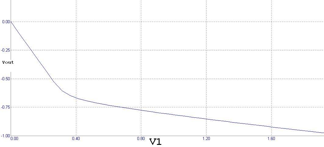
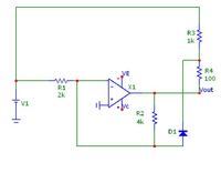
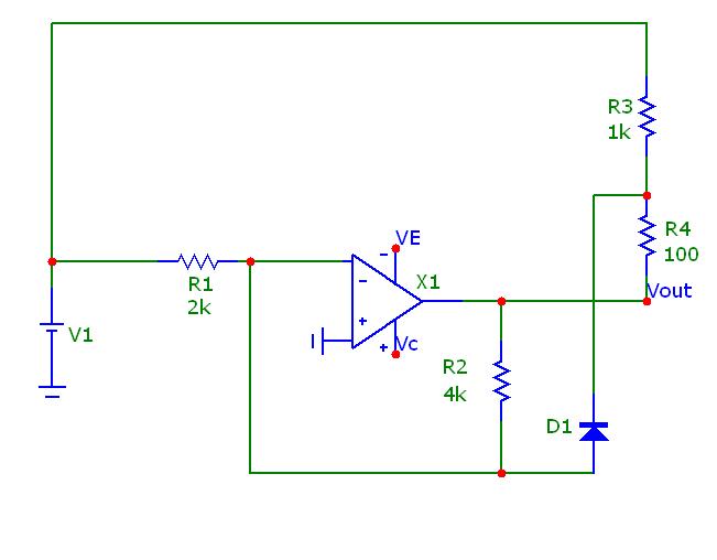
I have the schema. When the voltage opens diode resistor R4 is connected in parallel to R2 and amplification is changed.

But diode is temperature dependent. How can I cancel this temperature dependence?

Thank!


If you bias the other input of the OP amp with a diode to earth with some current flowing through(1mA?) it and readjust the resistors on the other diodes. Both diodes should then drop the magic 2.5mV/deg so the effects on the op amp can be minimised.
Frank
 

The solution will also affect output zero, adding a temperature dependant offset. Generally, a compensation diode is the right way. But the shown cicruit doesn't allow to simply add a compensation diode. A straightforward deign approach would be to specify the intended characteristic and required accuracy, and choose an appropriate circuit. For an exact temperature compensated function network, you need an active OP circuit for each segment of the characteristic.
 
.... bias the other input of the OP amp with a diode to earth.....

Thank, I tried it, but without success, may be something was wrong, I will try it again.

---------- Post added at 07:19 ---------- Previous post was at 07:16 ----------


Thank. OK, I thought so, but I try to look for simple solution.

---------- Post added at 07:23 ---------- Previous post was at 07:19 ----------

What is the circuit supposed to do.

This to do :) :


- when the diode is open, the amplification is changed.
 

Basically, a circuit like this:


The current bias transistor that feeds the reference diode should be made as low as acceptable, the other resistors have to be calculated for correct threshold and output offset.
 
Ouu, thank :) I will try it............

.............. after some time........ OK, thank, it is good inspiration ;-)
 
Last edited:

Status
Not open for further replies.

Similar threads

Part and Inventory Search

Welcome to EDABoard.com

Sponsor

Back
Top