Continue to Site

Welcome to EDAboard.com

Welcome to our site! EDAboard.com is an international Electronics Discussion Forum focused on EDA software, circuits, schematics, books, theory, papers, asic, pld, 8051, DSP, Network, RF, Analog Design, PCB, Service Manuals... and a whole lot more! To participate you need to register. Registration is free. Click here to register now.

TDA2030 active cross over circuit;Transistor getting heated up

Status
Not open for further replies.

jovin555

Advanced Member level 4
Joined
May 20, 2012
Messages
115
Helped
0
Reputation
0
Reaction score
0
Trophy points
1,296
Activity points
2,036
I am trying to build the active cross over circuit of TDA2030 given in Page 9 in the attached pdf.When i power up the circuit with 12V input power supply,The pnp transistor BD908 is getting heated up.(I am using TIP42C instead of BD908).Can anyone let me know why this is happening.I have connected a 4ohm output resistive load for testing purpose.I am also using a heat sink for all the TDA2030 and transistors.
 

Attachments

  • TDA2030.pdf
    207.8 KB · Views: 149
Last edited:

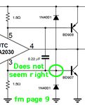
I can't help thinking the schematic has a mistake in the biasing arrangement of BD908 & BD907. It appears that supply current for the IC goes directly through the B-E junctions of these transistors! The 1.5 ohm resistors may drop less than 0.6V at 400mA, thus drawing that current through the 1.5 ohms (rather than the transistors). This doesn't look entirely right, however. I'm not an expert, so I could be wrong.

- - - Updated - - -

In fact page 5 has a similar arrangement, drawing power through the B-E junctions. However the component arrangement is not exactly the same as the page 9 schematic. You should compare these, on the chance page 5 is correct.

- - - Updated - - -

This could be an error. Page 9 has the collector and bias (BD907) directly connected.

2030 crop b.png

- - - Updated - - -

It should be wires overlapping, not joining.
 
As you have mentioned,the diode should be connected to the output only (pin 4)as shown in page 5.Anyways i will try this change and will let you know the result.
 

I have attached my sch and pcb files.I haven't connected the diode to the base of npn transistor as you can see in the schematics.Do i need to connect C8 in my schematics in the opposite direction?
 

Attachments

  • amp.rar
    52.6 KB · Views: 123

Good grief! You did not notice that many IC amplifiers are boosted like that?
Guess what? The BD908 is an ordinary single PNP transistor but the TIP142 is an NPN darlington dual transistor that is completely different!.

The shorted schematic is from Unisonic in Taiwan (China). The TDA2030 was invented by ST Micro in Italy and their original schematic does not have the Chinese short circuit.

I ALWAYS look at the datasheet from the inventor of an IC, not from a Chinese copy-cat.
 

But i am using TIP42 which is a normal pnp transistor.TIP42C and TIP41C can be used instead for BD908 and BD907 right?
 

You used an NPN TIP142 darlington to replace a BD908 PNP ordinary transistor. Yoo cant doo dat!
If you use darlingtons then you must bias them as darlingtons, not as ordinary transistors. And do not replace a PNP with an NPN. And do not use a Chinese datasheet of an Italian IC.
 

Attachments

  • TIP142.png
    TIP142.png
    18 KB · Views: 139

I ddn't use TIP142. I used TIP42. What you are referring is 142 but what am using is 42.
 

I ddn't use TIP142. I used TIP42. What you are referring is 142 but what am using is 42.
I am sorry, I read it wrong.
The circuit should work fine when you remove the Chinese short circuit which might have destroyed the IC and a few transistors.
 

What do you mean by short circuit?should i change tda2030 to a newer one?
 

What do you mean by short circuit?should i change tda2030 to a newer one?

YOU MUST remove the connection as shown by BradtheRad in post #2 within the green circle. It is unlikely to damage the IC.
 

I am unable to open the file- can you please post a jpg? There is a font problem...
 

I have attached the pdf file of schematics and board file.

The circuit is working fine now.i have reversed the position of capacitor C8 shown in the schematics.Now the +ve side of the capacitor is placed to the input of the audio signal.But i don't understand why changing the capacitor position made it work.Can anyone explain me this?


Everything is working fine now.The only thing is the TDA2030 for the mid range amp is getting a little bit heated up than the other two and also the mid range output is not so good.

Currently am using a 4ohm speaker to check the output of woofer,mid range and tweeter.Also there is a lot of hum at all outputs.How can i reduce the hum at the speaker output?I am using a 12-0-12 output transformer.Only the +12V and ground is attached to the amplifier power supply.I havn't used a regulator yet for 12.So the transformer output is going upto a maximum of 16V.Only a 2200uF capacitor is added at the output of the transformer.Do i need to add a 0.1uF at the transformer output to reduce the hum?
 

Attachments

  • amplifier.pdf
    21 KB · Views: 136
  • amplifierboard.pdf
    81.3 KB · Views: 125

That capacitor (C8) is expected to be a unpolarized (non-electrolyte type) one; although much of the input is positive, some could be negative too. The capacitor will handle the positive part of the signal well but load the negative going parts. If you do not have a 1uF unpolarised one handy, you can just use two of these back to back.
 
Last edited:

Your values for C11 and C12 are 10 times too high so maybe it causes the midrange amplifier to oscillate.
I agree that a non-polarized film capacitor should be used for C8.

A power amplifier does not need a voltage regulator that reduces the voltage and limits the current. The transformer needs a full wave rectifier module but instead you said you have a 2200uF capacitor connected to the transformer that is wrong. this power amplifier needs a filter capacitor that is much more than only 2200uF, maybe 10000uF or more. Please post a schematic of your power supply that causes the hum.
 

First you need to ensure that hum is not coming from the input.
 

First you need to ensure that hum is not coming from the input.
Also the input cable should be a shielded audio cable. Unplug the amplifier's input cable from the signal source. If the hum stops then the hum was from the source. If the hum remains then it is caused by an input cable with no shield or by the amplifier power supply.
 

I have removed the input source.Still there was hum.After isolating the resistors R13 and R17,there was no more hum.I don't know the reason why isolating the resistors removed the hum.

Also earlier I posted after reversing the direction of C8,Solved the issue of transistor getting heated up.But it was not the actual reason.I have reverted back the position of C8,Still the amp is working.

The body of tda2030 and the transistors were connected to the heat sink.So it was getting short.After isolating the transistor from the heat sink, the heating up issue was solved.Now am not using any heat sink for the transistors.Does it really require heat sink since the output is switching,it wont dissipate much power .is this correct?
 
Last edited:

Status
Not open for further replies.

Similar threads

Part and Inventory Search

Welcome to EDABoard.com

Sponsor

Back
Top