rosmawati
Member level 1
- Joined
- Jan 5, 2009
- Messages
- 34
- Helped
- 2
- Reputation
- 4
- Reaction score
- 1
- Trophy points
- 1,288
- Location
- Penang, Malaysia
- Activity points
- 1,542
Hi,
I need to ask a question regarding car audio amplifier.
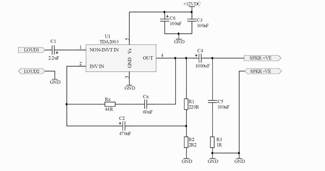
Actually I want to connect an audio amplifier so it can amplify any signal coming from my GSM module which 8 Ohm impedance and what I did was connect the differential line LOUD1 and LOUD2 to the input of the amplifier. As LOUD1 to the non-inverting and LOUD2 to inverting input
Nothing came out except those irritating noise when connected to the GSM module.
The amplifier module amplifies good sound when I connected it to mp3 player.
Did I choose the wrong amp IC?
Any please help me.:-(
I need to ask a question regarding car audio amplifier.
Actually I want to connect an audio amplifier so it can amplify any signal coming from my GSM module which 8 Ohm impedance and what I did was connect the differential line LOUD1 and LOUD2 to the input of the amplifier. As LOUD1 to the non-inverting and LOUD2 to inverting input
Nothing came out except those irritating noise when connected to the GSM module.
The amplifier module amplifies good sound when I connected it to mp3 player.
Did I choose the wrong amp IC?
Any please help me.:-(