Continue to Site

Welcome to EDAboard.com

Welcome to our site! EDAboard.com is an international Electronics Discussion Forum focused on EDA software, circuits, schematics, books, theory, papers, asic, pld, 8051, DSP, Network, RF, Analog Design, PCB, Service Manuals... and a whole lot more! To participate you need to register. Registration is free. Click here to register now.

[SOLVED] Systematic Cyclic Encoder in VHDL

Status
Not open for further replies.

Morell

Member level 1
Joined
Dec 1, 2015
Messages
35
Helped
0
Reputation
0
Reaction score
0
Trophy points
6
Activity points
614
Hi,


I'am a hardware engineer and my final project is
implemention of systematic cyclic encoder on a FPGA-Board.

I really need help in writing the code and
I would appriciate if you could help me with this matter.

1- Here are the facts about this problem:

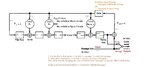
- We need a k bit message which we call U.
- U is the serial input of the encoder.
- GP stands for n-k bit Generator Polynomial.
- GP and U are going to build an N bit codeword which we call V.
- V is the serial output of the encoder.
- n and k are not fixed or constant this means that Generator Polynomial is not constant either
So (This is the major part and is really confusing to me) we have to build the encoder circuit
dynamically.

2- Attached file is the schematic of the encoder
Systematic Cyclic Encoder EDABOARD.jpg

3- Here is my code which I'm Sure is wrong.


Code VHDL - [expand]
1
2
3
4
5
6
7
8
9
10
11
12
13
14
15
16
17
18
19
20
21
22
23
24
25
26
27
28
29
30
31
32
33
34
35
36
37
38
39
40
41
42
43
44
45
46
47
48
49
50
51
52
53
54
55
56
57
58
59
60
61
62
entity OEncoder_1 is
     
     Generic    (: integer range 0 to 10 :=4;   -- K bits for Message
             N  : integer range 0 to 20 :=7);  -- N bits for Codeword
             
         Port ( 
            UTemp : in STD_LOGIC;
            SentU  : out STD_LOGIC;
                Clk      : in  STD_LOGIC);
              
end OEncoder_1;
 
architecture Behavioral of OEncoder_1 is
 
--Component Declaration
Component D_FF 
    Port ( D : in  STD_LOGIC;
           CLK : in  STD_LOGIC;
           Q : out  STD_LOGIC;
           rst : in  STD_LOGIC);
end Component;
 
--Signal Declaration
Signal GP : STD_LOGIC_VECTOR ((N-K) downto 0) :="1101"; -- Generator Polynomial
Signal i : integer range 0 to (N-K) := 0;                  -- Index on GP's Bits
Signal j : integer range 0 to (N-K) := 0;                  -- Index on IOX
Signal IOX : STD_LOGIC_VECTOR ((N-K) downto 0) :="0000";  
Signal GTemp : STD_LOGIC;
Signal Disable : STD_LOGIC := '1';
 
type Switch is ( SC , OC );     -- Short circuit and Open circuit
Signal SW : Switch := SC;     
 
begin
 
Process (CLK)
Begin 
  if( CLK'event and CLK ='1') then
 
    if(i < (N-K)) then 
                    
      if(GP(i) = '1') then
        U1: D_FF  port map(D =>(Gtemp xor IOX(j)) , CLK=>Clk, Q=>IOX(j+1) , rst=>Disable );                 
      else
    U2: D_FF  port map(D => IOX(j) , CLK => CLK , Q =>IOX(j+1) , rst => Disable );              
      end if;
    i <= i + 1;
    j <= j + 1;
        
    else    
    
      if(SW = SC) then 
        Gtemp <= IOX (N-K) xor Utemp;
    SentU <= Utemp;
      else -- SW = OC
    Gtemp <= '0';
    SentU <= IOX(j);    
      end if;
    end if;
  end if;
End Process;
end Behavioral;


4- Please help me with this.
Comments, advices, tips, links, a piece of code, anything!!!!

I would greatly apriciate your response
 

Well heres the first problems - you cannot instantiate a component inside a process - thats like trying to make a circuit that dynamically adds and removes chips to itself while it is running.

Instantiations take place outisde of a process.
 
  • Like
Reactions: Morell

    Morell

    Points: 2
    Helpful Answer Positive Rating
Thanks alot,

yeah i felt the same way, That is one of the reasons with which i know my answer is wrong :)

Thanks for your tip and your time
 

If you had compiled the code, the error would have been obvious.
Write yourself a testbench and simulate it to see if it behaves as expected.
 
  • Like
Reactions: Morell

    Morell

    Points: 2
    Helpful Answer Positive Rating
Yeah I did all that,
thanks alot :)
 

Are you sure you are supposed to implement dynamic n and k or make it parameterizable (i.e. generics in VHDL), that has been determined a priori. In the first case (dynamic) you'll either have to implement it with a upper limit on n-k, otherwise the logic can be infinitely large or it must be implemented as an algorithmic (software-like) implementation using an FSM, sacrificing performance with efficiency. In the second case you would just select the n and k and implement it for that specific case.
 
  • Like
Reactions: Morell

    Morell

    Points: 2
    Helpful Answer Positive Rating
hi,
1- thanks alot for your time and help

2- Wow!!! I forgot to tell you !!! 0<n,k<20 ; n>k; Thanks for reminding me :-D , sorry about that

3- Yes i am sure. N & k have to be generics.

4- Thanks for your response. It's much appriciated
 

3- Yes i am sure. N & k have to be generics.

This is all that maters, just make the design using a for loop to generate the n-k delay elements and taps. Just look for some generic digital filter VHDL code, which will do just that.
 
  • Like
Reactions: Morell

    Morell

    Points: 2
    Helpful Answer Positive Rating
"i" must be a variable in a for loop, otherwise only one bit in "D" can be calculated in each clock cycle.
It is also possible to skip the loop and just shift "D" and then xor with GP if Gtemp is '1'.

If N and K must be generics, the generator polynomial should also be a generic.

No generate loop is needed to do this.

No one instantiates a simple D_FF. Just write Q <= D in a clocked process.
For reset, do
if reset = '1' then Q <= (others >= '0');
in a proper place.
 
  • Like
Reactions: Morell

    Morell

    Points: 2
    Helpful Answer Positive Rating
Thanks alot std_match

I completely changed my design.

I will post the new codes a.s.a.p

Thank you for your response :)
 

Hi,


1- New code :


Code VHDL - [expand]
1
2
3
4
5
6
7
8
9
10
11
12
13
14
15
16
17
18
19
20
21
22
23
24
25
26
27
28
29
30
31
32
33
34
35
36
37
38
39
40
41
42
43
44
45
46
47
48
49
50
51
52
53
54
55
56
57
58
59
60
61
62
63
64
65
66
67
68
69
70
71
72
73
74
75
76
77
78
79
80
81
82
83
84
85
86
87
88
89
entity OEncoder_2v2 is
    Generic (: integer range 0 to 10 :=4;-- K bits for Message
                 N  : integer range 0 to 20 :=7-- N bits for Codeword); 
             
    Port ( 
              UTemp : in STD_LOGIC;
              SentU : out STD_LOGIC;
           Clk : in  STD_LOGIC);
              
end OEncoder_2v2;
 
architecture Behavioral of OEncoder_2v2 is
 
--Constant Declaration
Constant GP : STD_LOGIC_VECTOR ((N-K) downto 0) :="1101";   -- Generator Polynomial
 
--Signal Declaration
Signal D,Q : STD_LOGIC_VECTOR ((N-K-1) downto 0) :=(Others => '0'); -- Flip flop's Inputs
Signal ClockCounter : integer range 0 to N;
Signal GTemp,UQX : STD_LOGIC;
Signal Reset : STD_LOGIC := '1';


Type Switch is ( Parity , message );
Signal Switch2 : Switch := Message;
 
begin


-- taking care of FF's Input and XORs
    Gen1:for i in 1 to N-K-1 generate 
        D(i) <= (Gtemp xor Q(i-1)) when GP(i)='1' else
                     Q(i-1);
    end generate;
    D(0) <= Gtemp;
    
-- taking care of FF's Outputs
    UQX <= Utemp xor Q(N-K-1);
 
    
-- taking care of GATE
    Gtemp <= UQX when Switch2 = Message else
                '0';
 
-- taking care of Switch 2
    SentU <= Utemp When Switch2 = Message else 
                Q(N-K-1);
                
-- Sequential part 
Process(Clk,Reset,ClockCounter)
begin
 
    if( Reset = '0') then                           -- If #1
    
        Q <= (Others => '0');
        ClockCounter <= 1;
        Reset <= '1';
    else                                                    -- Else #1
        if (ClockCounter < N) then              -- If #2
        
            if(CLK 'event and CLK = '1') then   -- If #3
            
                Q <= D;
                ClockCounter <= ClockCounter + 1;
                
                if(ClockCounter = K)    then                -- If #4
                
                    Switch2 <= Parity;      
                    
                end if;                                 -- End #4
                
            else                                            -- Else #3
            
                NULL;
                
            end if;                                     -- End #3
        
        else                                                -- Else #2
        
            Null;
            
        end if;                                         -- End #2
        
    end if;                                             -- End #1
end Process;
 
end Behavioral;


2- This is the new Schematic
 

Attachments

  • Systematic Cyclic Encoder EDABOARD.jpg
    Systematic Cyclic Encoder EDABOARD.jpg
    287.1 KB · Views: 131
Last edited by a moderator:

Have you even tried looking at tutorial sites? Many of them have small examples of how to code FFs, muxes, etc.

This is not how you code sequential (clocked FF logic)

Code VHDL - [expand]
1
2
3
4
5
6
7
8
9
10
11
12
13
14
15
16
17
18
19
20
21
22
Process(Clk,Reset,ClockCounter)
begin
 
    if( Reset = '0') then                           -- If #1
          -- statements
    else                                                    -- Else #1
        if (ClockCounter < N) then              -- If #2
        
            if(CLK 'event and CLK = '1') then   -- If #3
                                --          
            else                                            -- Else #3
                                --
            end if;                                     -- End #3
        
        else                                                -- Else #2
        
            --
            
        end if;                                         -- End #2
        
    end if;                                             -- End #1
end Process;

This is the way you code a VHDL process that represents a bunch of FFs


Code VHDL - [expand]
1
2
3
4
5
6
7
8
9
10
11
12
13
Process (Clk,Reset)  -- Only Clk (and Reset if it is an asynchronous reset)
begin
  if( Reset = '0') then
    -- reset values
  elsif rising_edge(Clk) then -- the rising edge function call will correctly deal with 'Z' -> '1', 'X' -> '1' etc transitions
                              -- unlike the 'event code. Everything between this elsif and the end if is the synchronous stuff.
    if (ClockCounter < N) then
      -- do something while ClockCounter is < N
    else
      -- do this when ClockCounter is N
    end if;
  end if;
end Process;


My guess is you've done a lot of software in the past...

Making counters in hardware with a start value of 1 can be a waste of resources. e.g. a counter that must count from 1 to 16 will have to have 5-bits, but a counter that starts at 0 will count from 0 to 15, 16 counts, using only 4-bits.

- - - Updated - - -

And what is up with the NULL; statements? Don't use even use it.
 
  • Like
Reactions: Morell

    Morell

    Points: 2
    Helpful Answer Positive Rating
Dear ads-ee

wowwwwwwwwwwwwwww Thank you!!!!!
you really taught me alot!!!
And your guess was 120% right :-D
i will try your way
but there is something else about the clockcounter.

Here in Iran we don't have lots of boards and fpga because it is really expensive and
the university does not give us the budget to buy one and
the teachers themselves doesn't have any idea how to even Program the boards!!!!.
when we synthesize a code and it has lots of errors and warnings they do not know what to do :-D
and they just say put a "Null" there and there!!! :-D
right now after alot of searches, I've found a Spartan-3!!!!
here nobody knows what a spartan-3 even is!!!! :-D
so i do not have practical knowledge about this,
and at last because my english is not very good, it is really hard to learn this field for us :)
but thanks to U guys, I've already learned alot :)


would u mind giving me some links of those tutorial sites you were refering please?


so we always simulate
 

eh, this doesn't seem much different from the USA. Unless people have an interest in FPGA development, it will be very basic.

My favorite guide is the altera advanced synthesis cookbook from several years ago.

Otherwise, look at the device primitives. As an engineer, your goal is to write code that a synthesis tool will be able to map onto these. From there the synthesis tool coding recommendations will make sense.

This is vital as your designs expand. Knowing what can be done with registers vs "Distributed Memory" vs "Block Ram" vs "external" is important.
 
  • Like
Reactions: Morell

    Morell

    Points: 2
    Helpful Answer Positive Rating
Hi,
vGoodtimes

Oh my god. thanks alot !!!!
yes, you're right.
thank you for your response
 

Hi,

This is the latest one


Code VHDL - [expand]
1
2
3
4
5
6
7
8
9
10
11
12
13
14
15
16
17
18
19
20
21
22
23
24
25
26
27
28
29
30
31
32
33
34
35
36
37
38
39
40
41
42
43
44
45
46
47
48
49
50
51
52
53
54
55
56
57
58
59
60
61
62
63
64
65
66
67
68
69
70
71
72
73
74
75
76
entity OEncoder_3 is
    Generic (: integer range 0 to 10 :=4;-- K bits for Message
             N  : integer range 0 to 20 :=7);-- N bits for Codeword 
             
        Port          (UTemp : in STD_LOGIC;
             SentU : out STD_LOGIC;
                         Clk : in  STD_LOGIC);
      
end OEncoder_3;
 
architecture Behavioral of OEncoder_3 is
 
--Constant Declaration
Constant GP : STD_LOGIC_VECTOR ((N-K) downto 0) :="1101";   -- Generator Polynomial
 
--Signal Declaration
Signal D,Q : STD_LOGIC_VECTOR ((N-K-1) downto 0) :=(Others => '0'); 
Signal ClockCounter : integer range 0 to N;
Signal GTemp,UQX : STD_LOGIC;
Signal Reset : STD_LOGIC := '1';


Type Switch is ( Parity , message );
Signal Switch2 : Switch := Message;
 
--Type Mode is (Idle, Encoding);
--Signal Current : Mode := Idle;
 
 
begin


-- taking care of FF's Input and XORs
    Gen1:for i in 1 to N-K-1 generate 
        D(i) <= (Gtemp xor Q(i-1)) when GP(i)='1' else
                     Q(i-1);
    end generate;
    D(0) <= Gtemp;
    
-- taking care of FF's Outputs
    UQX <= (Utemp xor Q(N-K-1)) When Utemp = '0' else
             (Utemp xor Q(N-K-1)) When Utemp = '1' else 
             '0';
 
    
-- taking care of GATE
    Gtemp <= UQX when Switch2 = Message else
                '0';
 
-- taking care of Switch 2
    SentU <= Utemp When Switch2 = Message else 
                Q(N-K-1);
                
-- Sequential part 
Process(Clk,Reset)
begin
 
    if( Reset = '0') then
 
        Q <= (Others => '0');
        Reset <= '1';
        ClockCounter <= 0;
        
         elsif rising_edge(Clk) then
    
            Q <= D;
        ClockCounter <= ClockCounter + 1;
        if (ClockCounter = K) then 
            Switch2 <= Parity;
        end if;
 
         end if;
end process;
end Behavioral;

 
Last edited by a moderator:

The main criticisms are minor. For example, you should have a consistent indentation scheme. This makes code readable. My mentioning this is normally bad practice, but you seem to want feedback.

RTL developers prefer to have modules with registered outputs and inputs when possible. This makes the design easy to use as logic paths start and end in the module -- unaffected by external modules. This is a best-practice.

Switch2 is not reset. This means "reset" is now a clock enable for this signal. In this case you want it to be a reset. In other cases this can result in slower logic as clock-enable is often a useful and free input for FPGA designs. If clock enable is used by accident, then extra inputs are added to the logic driving the input to the register.

- - - Updated - - -

Actually I take that back. You have an async reset that deasserts reset! Reset should be an external input.
 
  • Like
Reactions: Morell

    Morell

    Points: 2
    Helpful Answer Positive Rating
Hi,
@vGoodtimes

thanks alot for your response :)
You are a great mentor :)

1- What do you mean when you mentioned "Consistent indentation scheme"?
you mean an attached schematic file?

2- Reset is an external input, but i forgot to do that.

3- i didn't quiet understand the switch2 part :)
 

1 - for example, you have some items indented by multiples of four spaces, some by other amounts. My guess is a mixture of tabs and spaces in your original file allows the file to look correctly on your screen, but not when copied/pasted.

3 - switch2 is not in the (reset = '0') branch. as a result, it must retain its current value during a reset. This means switch2 is only loaded when (reset = '1') -- reset is acting like a "clock-enable".

In FPGA designs, FF's have a clock enable and a reset built in. Higher performance designs will make good use of these extra inputs. For your case, the next-state input is now "NextSwitch2 = Parity when (ClockCounter = K) else Switch2" with a clock-enable of (reset = '1'). Without the reset issue, the logic becomes "NextSwitch2 = Parity" with a clock enable of "(ClockCounter = K)".
 
  • Like
Reactions: Morell

    Morell

    Points: 2
    Helpful Answer Positive Rating
vGoodtimes
I have another question about this sentece that you mentioned earlier.
"RTL developers prefer to have modules with registered outputs and inputs when possible."

So you mean that I have to store Utemp (which is a serial input) in A FF first?
and then just use the FF instead?
it is like causing a delay (for one clock pulse)

is that what mean?
 

Status
Not open for further replies.

Similar threads

Part and Inventory Search

Welcome to EDABoard.com

Sponsor

Back
Top