Continue to Site

Welcome to EDAboard.com

Welcome to our site! EDAboard.com is an international Electronics Discussion Forum focused on EDA software, circuits, schematics, books, theory, papers, asic, pld, 8051, DSP, Network, RF, Analog Design, PCB, Service Manuals... and a whole lot more! To participate you need to register. Registration is free. Click here to register now.

synchronous counter circuit to convert analog to digital

Status
Not open for further replies.

greenjuice

Member level 1
Joined
Aug 21, 2015
Messages
40
Helped
0
Reputation
0
Reaction score
0
Trophy points
6
Activity points
348
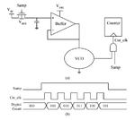
Actually i make ADC as attached image.

But i have some problem.

Period of VCO I designed is 0.3ns - 0.275ns at 0 - 1V input voltage.

But 12bit counter circuit I designed doesn't work below 3ns period. So they don't match.

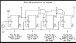
I designed synchronous counter circuit using this.(I attach synchronous counter circuit I used)

Is it possible to design the synchronous counter circuit on similar performance of my VCO?

I think it is impossible in that if the clock cycle become shorter, it is difficult for each jk flip-

flop in counter to toggle at a proper time by its transition delay time.

What do you think? please help me.
 

Attachments

  • synchronous counter circuit.png
    synchronous counter circuit.png
    45 KB · Views: 110
  • vco+.png
    vco+.png
    20.4 KB · Views: 106
Last edited:

330 MHz maximum counter clock sounds fair. So you'll either design a VCO with lower output frequency or dedicated prescaler that is able to handle the high clock frequency.

I would expect other ADC principles than VCF to be used, e.g. SDM.
 

I redesigned my counter circuit, changing d flip flop in jk flip flop.

I used tspc d flip flop. It has much shorter transition delay than former one.

so It works on 454MHz now. But I think it is impossible for this circuit to work on more than 1GHz in this way.

And this is my graduation work. So fortunately, I can't change my direction(VCF).

Thank you for your advice.


asynchronous counter signal.pngasynchronous counter circuit.pngOh, is it possible to design asynchronous counter circuit on 4GHz?

Actually, I designed asynchronous counter circuit at first(attached image 1).

But each counter signal has delay like attached image 2. So I decided to design synchronous counter circuit.

If it is possible to design asynchronous counter circuit on high frequency(more than 1GHz),

could you teach me the points to be careful?

And do you think asynchronous counter circuit works properly

when you see asynchronous counter signal, attached image 2?

Thank you for your advice.
 

In addition,

In case of aysnchronous counter circuit,

each output of counter circuit has delay because each jk flip flop is output of previous jk flip flop.

So I decided to design synchronous counter circuit.
(synchronous counter circuit has same clock timing. So I think it minimize delay problem)
 

I understand the asnchronous counter suggestions this way:

- use prescaler made as asynchronous counter
- implement a synchronous counter at moderate speed

Probably the only way to save your high frequent VCO.
 

Designing a very high frequency counter circuit is very difficult and you will end up with very low difference in digital values.

Better try to construct a low frequency VCO with high variation in frequency.

I think you can simply design a VCO using 555 or 565 IC(I already did that once).
 

Status
Not open for further replies.

Similar threads

Part and Inventory Search

Welcome to EDABoard.com

Sponsor

Back
Top