Continue to Site

Welcome to EDAboard.com

Welcome to our site! EDAboard.com is an international Electronics Discussion Forum focused on EDA software, circuits, schematics, books, theory, papers, asic, pld, 8051, DSP, Network, RF, Analog Design, PCB, Service Manuals... and a whole lot more! To participate you need to register. Registration is free. Click here to register now.

Switching circuit for piezo circuit

Status
Not open for further replies.

hangtime21

Newbie level 1
Joined
Jan 30, 2012
Messages
1
Helped
0
Reputation
0
Reaction score
0
Trophy points
1,281
Activity points
1,288
We need to make a switching circuit. It involves a piezoelectric material charging a series of capacitors. When the capacitors reach 12v or more the switch would turn on to the charge controller. The charge controller needs 12v to work. We've tried some fets with voltage divider from the charged capacitors going to the drain and gate but couldn't get it right. What happens is the output voltage goes up as the input voltage to the gate goes up rather than a surge of voltage at a certain Vin.
 
Last edited:
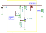
You may use a P-MOSFET and a TL431, see the diagram:
 

Attachments

  • 12 V_on_off.GIF
    12 V_on_off.GIF
    15.7 KB · Views: 95
  • Charge control.GIF
    Charge control.GIF
    13.5 KB · Views: 93
Status
Not open for further replies.

Similar threads

Part and Inventory Search

Welcome to EDABoard.com

Sponsor

Back
Top