Continue to Site

Welcome to EDAboard.com

Welcome to our site! EDAboard.com is an international Electronics Discussion Forum focused on EDA software, circuits, schematics, books, theory, papers, asic, pld, 8051, DSP, Network, RF, Analog Design, PCB, Service Manuals... and a whole lot more! To participate you need to register. Registration is free. Click here to register now.

[SOLVED] Switching a remote controller

Status
Not open for further replies.

deadbird

Newbie level 3
Joined
Oct 13, 2012
Messages
3
Helped
0
Reputation
0
Reaction score
0
Trophy points
1,281
Activity points
1,301
Hi there ;)

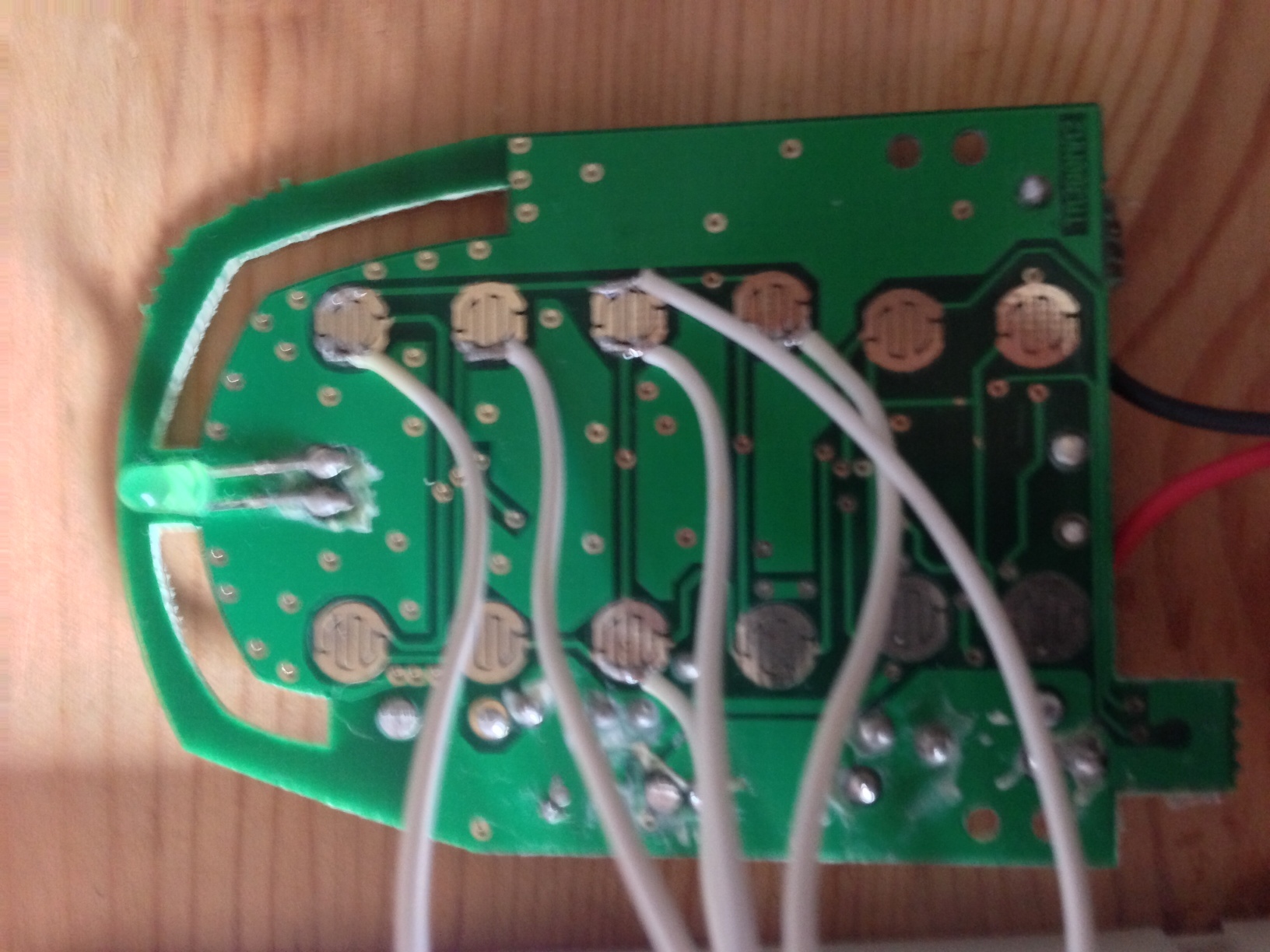
I need some advice: i'm trying to control a remote controller, i'd like an arduino to act as "the user pressing buttons". Is there a way I can use transistor or 4N32-like optocouplers to simulate button press?

Thanks in advance ;)
 

Probably. Does the remote control have a lot of buttons and a matrix of contacts? Then it might be easier to use something like a 4066 chip. It's basically a digitally controlled, quad analogue switch, so you should have no problems about the voltage the remote controller uses or how it strobes the matrix.

Just connect one of the 4066's 'switches' across the key contacts you want to control, make sure to have a common ground connection, and take the switch control line high for long enough for the strobe to pass it (a few tens of ms is probably enough, maybe longer).
 

Basically, it's a tiny remote, used to remote control power supply units. It has 4 "on" buttons (one per unit to control), 4 "off" buttons, one "all on" and one "all off".

On the PCB, there's one "switch off" and a "switch on" track, all I have to do is connect a button either to "switch on" or "switch off" track. Here's a picture of it:


So I guess 4066 would to the trick, but I've never used any. Does it act as a transistor?
 

I have a similar control unit in my living room connected to lights.

The 4066 (probably you would use a 74HC4066 or 74HCT4066) is much easier than a transistor, think of it like a relay that closes its contacts together when you energize the coil. In this case the contacts don't move and energizing is as simple as giving a logic high to the control input. The limit is that it can only switch low voltages and currents, but that is fine here.The 4066 has four such switches, so you would need three chips.

You could use transistors but personally I would use 4066 chips for this, provided...

...do you have a 50ohm (or close to it) resistor handy? See if putting that across one of the button contacts will switch it on. The 4066 has about that amount of resistance when turned on. I'm guessing it will work fine, but just check before you go to the effort of getting and wiring up the 4066.

This is a datasheet for a version of the 4066. If you don't understand most of it, don't let it bother you. For this simple application the only important things are the power supply it needs (from your Arduino : 5v?), the 'on' resistance (about 50 ohms) and the pinout.

**broken link removed**
 
I checked the datasheet you mentioned, I seems that this buddy will fit perfectly. Arduino outputs 0-5V on digital pins. I tried a 56 ohms resistor, it works perfectly. Even with 47k :D

I think I'm going to order a bunch of these, but could you explain how I could achieve this using transistors? Knowing that the current that flows through each button is as low as a few micro amps?
 

Status
Not open for further replies.

Similar threads

Part and Inventory Search

Welcome to EDABoard.com

Sponsor

Back
Top