Continue to Site

Welcome to EDAboard.com

Welcome to our site! EDAboard.com is an international Electronics Discussion Forum focused on EDA software, circuits, schematics, books, theory, papers, asic, pld, 8051, DSP, Network, RF, Analog Design, PCB, Service Manuals... and a whole lot more! To participate you need to register. Registration is free. Click here to register now.

Switched capacitor stb simulation issue

Status
Not open for further replies.

venn_ng

Member level 5
Joined
Mar 26, 2017
Messages
87
Helped
1
Reputation
2
Reaction score
1
Trophy points
18
Activity points
645
Hi,

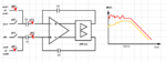
I am trying to run stability sims for a switched capacitor op-amp circuit as shown.

I tried both ac and tran stb (not evaluated pstb yet).

I observe that in some corners, the frequency spectrum @ low frequencies (<10kHz) has weird issues.

Do you know what is causing this and how to solve this?

I tried enabling dc pivot check and pivot. Doesn't solve the issue. Also tried placing a 1G resistance parallel to C2 to provide dc feedback path; doesn't solve the problem either.
 

Attachments

  • stability_sim_issue.png
    stability_sim_issue.png
    40.5 KB · Views: 209

Trying to run small signal analysis on a large
signal switched circuit tends to bring trouble.
What is the valid DC solution to begin with?
Do you have some sort of state-space
equivalent for the switch+cap+clock "chunks"
that are DC- and small-signal solvable
(solvable, validly, that is)?
 

I am able to make DC converge by placing a 1G resistance in the feedback path (parallel to C2).

How would you suggest to run stability checks on a switched cap circuit like the one I have?
 

DC convergence is only the first requirement.

The next is that the amplifier be in closed loop
operation, or you won't have the expected gain
and phase (maybe even none, if it's railed out).
If the clocks aren't running (large signal transient)
is the amplifier in its intended closed loop config?

For power supplies this problem is solved by "state
space average" models of the switching part of
the powertrain, while the linear bits are simulated
as-built.

I do not know if sampled-data folks use the same
approach or similar, or just go to a switched
capacitor simulator.

A fully differential amplifier wants fully differential
feedback. You say you only put one resistor across
one capacitor. Maybe an answer is to make the
feedback and input paths all resistors (suitably
high in value, not to load the output unacceptably,
suitably low that you don't pick up irrelevant poles
in the outer circuitry that affect operation)?
 

Status
Not open for further replies.

Part and Inventory Search

Welcome to EDABoard.com

Sponsor

Back
Top