Continue to Site

Welcome to EDAboard.com

Welcome to our site! EDAboard.com is an international Electronics Discussion Forum focused on EDA software, circuits, schematics, books, theory, papers, asic, pld, 8051, DSP, Network, RF, Analog Design, PCB, Service Manuals... and a whole lot more! To participate you need to register. Registration is free. Click here to register now.

[SOLVED] Switch on a BJT which switches on a MOSFET

Status
Not open for further replies.

Just-s

Newbie
Joined
Oct 25, 2021
Messages
2
Helped
0
Reputation
0
Reaction score
0
Trophy points
1
Activity points
75
Note that I don't have any experience in electronics so general tips and explanations are also appreciated.

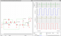
The goal is switch a 5v 1A DC motor with a logic level signal(eventually a microcontroller) powered by a 5v power supply.

To do this I originally got a IRF740 MOSFET. Since then I learned that at 4.5v Vgs it merely begins to switch on, but it is not enough to allow a 1A drain source current.

I know there exist "logic level MOSFETs" which are made exactly for that, but I am trying to work with the components I currently have.

I also have some BJTs and while none of them are capable of a 1A collector-emitter current I thought it should be possible to switch to switch the MOSFET with it.

The idea is: the MOSFETs gate is connected to the BJTs(2N3904) collector. The low current 3.3V input voltage is connected to the BJTs base. Emitter is connected to common negative rail.

However the MOSFET does not seem to be switched on. If i replace the MOSFET with an LED it lights up, so I'm confident that i got that part of the circuit right.

Additional questions:
1. When the BJT is off, I measured the collector/emitter voltage, it was around 4 volts. Is it normal? Can a voltage exist without current?
2. As I understood, the MOSFET is a voltage operated device, does that mean the current at it's gate doesn't matter at all/is not necessary?
 

SHOW YOUR SCHEMATIC!!!

First of all, using a BJT is not going to magically boost the gate voltage. The IRF740 needs up to 4V just to START to turn on. Thus, you're going to need something like 10V from somewhere; it's not going to come out of the BJT, and 5V is probably not enough to turn the MOSFET fully on.

If you don't have anything higher than 5V, then this MOSFET is just not going to work. You can spend under a dollar (or Euro, or whatever you use) and get the proper part.

1) Without your schematic, there's no way to answer.
2) Gate current matters when you're dealing with high speed switching. For your application, it's not too important.
 

When you get further along you will find out that
it is as important, or more important in some cases,
to turn the MOSFET off.

Don't build yourself a "one legged man in an a$$
kicking contest".

Since your output and input voltages are the same
(5V) all you really want is to "buffer the current".
Like a 5V-output-capable MOSFET driver? There
ought to be some for driving "logic level FETs"
and these ought to have decent control of
shoot-through current. Find one rated for 6-10A
peak and it ought to be fine for 1A continuous.
 

SHOW YOUR SCHEMATIC!!!

First of all, using a BJT is not going to magically boost the gate voltage. The IRF740 needs up to 4V just to START to turn on. Thus, you're going to need something like 10V from somewhere; it's not going to come out of the BJT, and 5V is probably not enough to turn the MOSFET fully on.

If you don't have anything higher than 5V, then this MOSFET is just not going to work. You can spend under a dollar (or Euro, or whatever you use) and get the proper part.

1) Without your schematic, there's no way to answer.
2) Gate current matters when you're dealing with high speed switching. For your application, it's not too important.
IMG_20211026_194741.jpg
See poorly drawn schematic. I was hoping that if 4V is the minimum, with 5V the MOSFET would open enough to get 1A through. But since I can't provide the 5V from my microcontroller I tried the BJT.

I think you answered it though: without 10V GS voltage it just won't work. In that case is the "logic level" MOSFET the right choice?

Hi

Yes.
Think about it: Your power outlet will have voltage even if you don't connect a vacuum cleaner.
The same is true for a car battery.

Klaus
Thanks! Great examples that I never really thought about 🤔

When you get further along you will find out that
it is as important, or more important in some cases,
to turn the MOSFET off.

Don't build yourself a "one legged man in an a$$
kicking contest".

Since your output and input voltages are the same
(5V) all you really want is to "buffer the current".
Like a 5V-output-capable MOSFET driver? There
ought to be some for driving "logic level FETs"
and these ought to have decent control of
shoot-through current. Find one rated for 6-10A
peak and it ought to be fine for 1A continuous.
Won't cutting the 5V to the gate turn it off? I might have missed the metaphor.

Although after reading this post I'm starting to doubt whether I under MOSFETs at all.... If a MOSFET holds a charge that needs to be dissipated to switch it off, wouldn't the DC motor do it in my case?

But it looks like a MOSFET driver solves everything I wanted to solve.
 
Last edited by a moderator:

Your schematic as shown won’t work, there’s never any voltage on the gate-it’s either floating or grounded through the BJT. For this to work you need a resistor from the gate to, say, 10V.

A MOSFET driver wont solve your problem unless it’s got some way of stepping up the voltage. But why add the complexity, just get a logic level MOSFET and you’re done. Something like IRFZ44. That’s probably overkill for your application, but they’re cheap and plentiful.
 

1635276455380.png


Typical circuit. Note missing is a ~ 10K from Q2 base to ground. thats so
when processor starts up (it typically floats, HiZ, it's pins) that Q2 does not
turn on from leakage current until processor takes control of its pin.

This schematic also missing freewheeling diode across motor, or a snubber.
This protects MOSFET from hi-V inductive turn off transient.

Anode to + Vsupply of motor, Cathode to its other side of winding, which
is connected to MOSFET drain in the above circuit.

Lastly in above circuit mosfet turns off, relatively, fast because Q2 quickly
discharges Q1 gate C. But turn on is slow due to R1, which increases Q1
power dissipation due to heat and the fact Q1 stays longer in its linear
region. So make R1 smaller, at most 1K. That will help. There are circuits
where another Qx can be added to replace R1 and make it a lot faster turn on
if needed.

1635277337246.png


This circuit can operate off single supply low voltage,. But I would simulate it first
to insure when micro pin is floating both Q1 and Q2 do not conduct and short out
supply. Normally one uses a two phase PWM with deadtime in its outputs to drive
the Q1 and Q2. Again circuit should have free wheeling diode connected across
motor (load), its not shown here.

Deadtime insures Q1 and Q2 are never on simultaneously at the same time causing
a direct short across power supply. Many micros have deadtime control for their PWMs.

1635277655958.png


Regards, Dana.
 
Last edited:

Connect your resistor between the gate/collector and the top of the battery. This will give you the voltage you need to fully turn the MOSFET on. Suggest a value of 2.2K. Make R1 about 470 Ohms and it should work. The logic will be inverted, a high at the input will turn the motor off, a low will turn it on, compensate for that in software.
I assume the negative side of the battery is also linked to the logic ground.

Brian.
 

Hi,

If you don't have 12v then you may use a voltage doubler using diodes and Cs.

Klaus
 

Hi,

The OP states he has a non_logic_level Mosfet .... and 5V at VGS won't drive enough motor current.
He also states he want's to use this Mosfet.
So for me the only solution is to drive the gate with higher voltage.

To make the microcontroller to output a square wave ...and connecting a few D, C and an R ..
could generate a 9.4V gate voltage.

Klaus
Interesting idea, worth a try. (But if it was me, I would have already bought and installed a logic-level MOSFET).
 

Hi,

If you don't have 12v then you may use a voltage doubler using diodes and Cs.

Klaus
How do you get a doubler with non inverted output and common ground ?
Without resorting to a transformer.....


1635330096866.png


Of course a switch cap V doubler would work -


Regards, Dana.
 
Last edited:


Hi,

Use the first schematic of the link of post#14.
C1=C2=10n
C3= 33n
D1, D2, D3 = BAT54
Rload = 100k
ON = 30kHz, 50% d.c., 0V, 5V
OFF = 0V

Result:
V_Gate = about 9V
t_on = about 1ms
t_off = about 5ms

IRF740 is considered fully OFF with V_GS <3V ...and fully ON with V_GS > 8V

Klaus
 

I tried it, with Si or Schottky's never get more than just under 5V.

I also suspect peak gate current driving current for MOSFET out of the question
for these circuits.

Note I drove input to pump with a V source, obviously from a micro output
even worse performance would occur.

1635340601619.png


I think these circuits a non-starter for consideration.


Regards, Dana.
 

That makes no sense to drive MOSFET gate directly from 5 V UP output, for
a number of reasons, Not the least of which its severely limited current to
drive mosfet gate. The whole point of using the NPN. And worst case MOSFET
only turned on for a couple hundred uA in its drain, its Rds still quite high.

The Rdson spec is at Vgs = 10V which is why you were looking at diode doublers.....

You cant mean this, right ?

1635345362368.png


Regards, Dana.
 

Attachments

  • 1635345321950.png
    1635345321950.png
    89.7 KB · Views: 104
Last edited:

Status
Not open for further replies.

Similar threads

Part and Inventory Search

Welcome to EDABoard.com

Sponsor

Back
Top