Continue to Site

Welcome to EDAboard.com

Welcome to our site! EDAboard.com is an international Electronics Discussion Forum focused on EDA software, circuits, schematics, books, theory, papers, asic, pld, 8051, DSP, Network, RF, Analog Design, PCB, Service Manuals... and a whole lot more! To participate you need to register. Registration is free. Click here to register now.

swaped E and H plane under CST

Status
Not open for further replies.

Nano_o

Member level 2
Joined
Mar 26, 2014
Messages
46
Helped
3
Reputation
6
Reaction score
2
Trophy points
8
Activity points
325
Hallo,
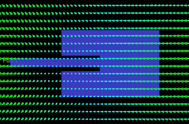
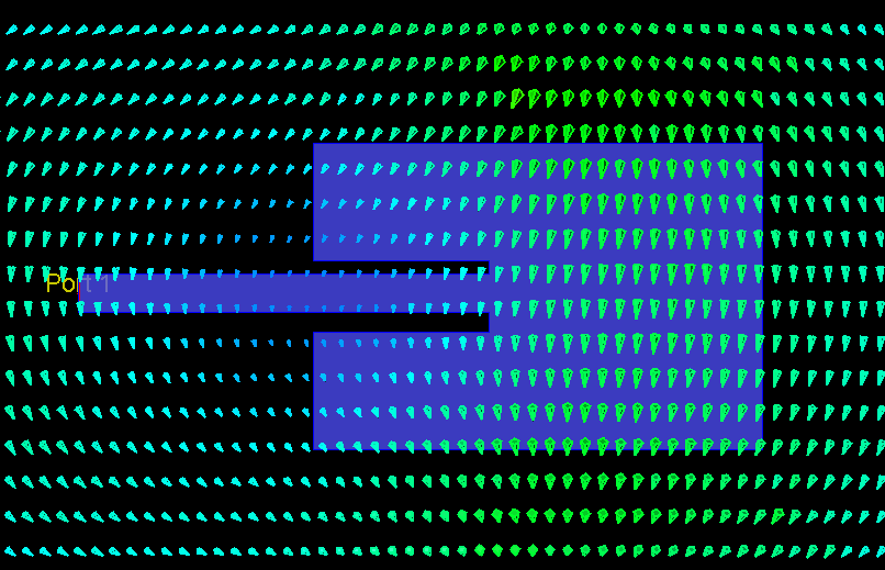
I have a loop monopole antenna while visualizing the E and H patterns I get them swaped (E must be H and
vice versa). Any ideas about what could cause such thing!
Note: I took E plane (phi=0º) and H plane (phi=90º)
Regards!
 

This is not possible. Please explain a bit more about your settings
 

well it is a very ordinary loop planar antenna with a partial ground plane.
I have attached the results that I get. PATTERN.png
thx!
 

well I am confused now more than I was, but one comment seems to solve the problem
What you get from measurements is results over azimuth angle and elevation angle, and you can easily make a mistake if you don't know the antenna PCB orientation. PCB rotated 90° on the antenna holder, and there it is, your E/H plane confusion.
by volker@muehlhaus.
what do you think?!
 

I did not used CST, but maybe there is a way to draw E and H planes in 3D. Or you can draw simplest possible monopole antenna and simulate it in CST, then see if things are still swapped. Just a guess: maybe E and H planes are fixed to X,Y,Z axis somehow, so things will be swapped if you draw PCB in XZ plane or XY plane or YZ plane. Another solution to see if CST have some examples on antennas, and see theirs E/H planes and orientation in XYZ space.

p.s. You can post image of your antenna in 3D view in CST, especially if there are some axis/planes drawn, so experienced CST users easily determine where they usually measure E/H patterns.
 

thank you !
please find attached the patterns in 3D
perspectiveView.pngxz_plane.pngyz_plane.png
 

few things must be clarified:
1) What are theta and phi and how they related to E-plane and H-plane.
there is a nice image in this topic:
https://www.edaboard.com/threads/242762/
65_1330619143.gif

From this image:
H-plane, angle is phi, it is horizontal plane
E-plane, angle is theta, it is vertical plane

Come back to your image:
broken link removed
If CST use similar angle names for E/H plane, then
Theta horizontal -> E-plane is horizontal
Phi vertical -> H-plane is vertical
So it looks reversed to me.
On the first image E-plane is vertical, and on your image it looks like E-plane is considered horizontal

2)We must know where E-plane and H-plane must be on your antenna
as on volker@muehlhaus for patch-images:
E-field and H-field vectors:
7613800800_1430406903.png

1283328400_1430406903.png

if feeding port is on the right, then E-plane is horizontal. But usually feeding port is considered vertical (at the bottom), then E-plane would be vertical.

So i think we are pretty near to understand how swapping is occurred. The only thing left is to clarify how your antenna looks like (it is not clear from image), to understand where real E-plane is, and is it in horizontal position. If your antenna's E-plane is vertical, then result probably swapped, because in 3D view E-plane considered horizontal.

Problem arises from the fact that CAD software does not automatically determine antenna polarization (i guess so).

p.s. in volker@muehlhaus patch images there are E-field and H-field vectors. Probably CST can do it. But it is also can be deducted from knowledge on your antenna configuration.
 
Last edited by a moderator:
  • Like
Reactions: Nano_o

    Nano_o

    Points: 2
    Helpful Answer Positive Rating
thank you very much!
I feel like confused about the figures of volker they don't tell much to me :-(
ant_edaborad.png
Ps: could you please specify the planes by xy and yz the terms horizontal and vertical depends on the structure positioning.
thx!
 

What is polarization of this antenna? I guess it have vertical polarization.
I think that on your images phi is angle through XY plane, which gives H-plane pattern.
And theta is angle through XZ plane, which gives E-plane pattern.
If i am correct, all you need is to put your antenna substrate in YZ plane like this:
yz.png
but i am not sure. There must be some convention about E/H-planes and phi/theta angles in CST, or some configuration.
 
  • Like
Reactions: Nano_o

    Nano_o

    Points: 2
    Helpful Answer Positive Rating
Status
Not open for further replies.

Part and Inventory Search

Welcome to EDABoard.com

Sponsor

Back
Top