Continue to Site

Welcome to EDAboard.com

Welcome to our site! EDAboard.com is an international Electronics Discussion Forum focused on EDA software, circuits, schematics, books, theory, papers, asic, pld, 8051, DSP, Network, RF, Analog Design, PCB, Service Manuals... and a whole lot more! To participate you need to register. Registration is free. Click here to register now.

[SOLVED] Suppress initial high pulse on output

Status
Not open for further replies.

ard

Full Member level 5
Joined
May 3, 2009
Messages
251
Helped
52
Reputation
104
Reaction score
50
Trophy points
1,308
Location
Mumbai, India
Activity points
2,783
Hello all,

I have a microcontroller driving a relay from one of its io pins.

My code, hardware works fine, except for one small, but critical issue.

When I switch on the circuit, all pins of the controller (regardless whether they're set up as inputs or outputs), flash high for a few milliseconds before the code takes over and they settle low.

While this might not be an issue in most applications, in my case this is unacceptable, as the pin drives a solenoid to open a door.

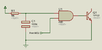
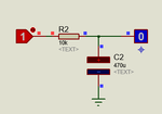
How can I suppress this? A 555 delay trigerred by the output, and then driving the solenoid? I'm hoping somebody could suggest a simpler transistorised solution.

Regards.
 

Have you tried placing a diode across the relay coil ?
That will suppress the high back EMF voltage, and might fix the problem.
 

Yes, there is a diode across the coil. BUT, this problem occurs even if the io is not connected, so it is not caused by anything external; its an intrinsic issue with the controller that it initially gives a high burst to all the ports.
 

It sounds like either the ground or supply are bouncing somehow.
May be a layout or wiring/grounding problem, or maybe some better decoupling ?
 

I disagree.

The symptoms suggest there is a delay between applying the power source and the microcontroller pins being set to a defined state. It's difficult to diagnose without a schematic and a copy of the software but the first place to look is the reset circuit. It could be simply that the reset is too slow and a change of component values would fix it.

If that isn't the problem, the next check would be the initialization of the port pins in the program, for example, does it do something that takes a long time before configuring the pins?

As a final resort, if there are any spare pins, use two together, invert one then AND it with the other so they have to be in opposite states to operate the relay.

Brian.
 

Brian, I think you are on the right track concerning the problem.

But, I'm afraid your solution would not work, as this positive pulse on the whole port happens *before* the code starts running.

I've even observed this phenomenon on a fresh controller without any firmware written, as also on one with my code, where the pins are set as outputs, and then driven low, immediately. Also tried configuring the pins to come up as inputs on startup, and then change them into outputs. Therefore, no0 amount of changes in the code would help, including the ANDing that you suggested.

The chip in question is the ESP8266. The reset, as per the specs has been pulled high (connecting it directly to Vcc does not help, nor adding a capacitor to raise it slowly).

The only answer seems to be to let the controller pulse out its initial flash, and then use a short pulse ignorer between the output and the load. A 555 or a transistorised version, perhaps?

Anand
 

You didn't show your actual circuit.

General speaking, unwanted pulses during processor power on occur if the driver circuit isn't designed according to the processor behaviour.

E.g. a 8051 drives out high (by the internal weak pullup) before the code starts control. So it can be only safely operated in active low configuration, which may require an external inverter. But most processors power up with ports in tristate mode and can be pulled to low or high idle state by external resistors.
 

The only ESP8266 I can find reference to is a Wi-Fi module. If that's what you are using it is no wonder you have problems, you will have to interface it to another controller and let that control the relay.

Brian.
 

The ESP8266 is indeed a wifi module, but with a powerful RISC processor on board. As you point out, you can use it with another controller.

OR, since it already has a powerful controller on board, besides the wifi radios, one can use the controller by itself, by flashing an alternate firmware, overwriting the stock. In my case, I have re-flashed the module with Lua, which enables one to design standalone systems directly on the ESP8266. Lua+ESP8266 make a very powerful, compact and cheap (the wifi module sells for less than US$ 3) combination for wifi enabled projects.
 

Are you using 8051 MCU ? If yes, the POR state of 8051 port pins are high. If you are using a NPN transistor to drive the solenoid then this problem occurs. So, you have to use PNP transistor to drive the solenoid and invert the Relay ON/OFF value in the code.
 

Did you try to operate the ESP8266 I/O port with pull-up or pull-down resistors, optionally with inverted (active low) level?
 

No, I'm using no controller besides the ESP8266 itself. Anyway, what you said about the 8051 applies here as well, but using a pnp is not an option, as my relay is a 6 volt device, and the ESP8266 runs at 3.3

Thanks anyway.

AND! I solved the problem, brute force! I fed that signal into a 12F675 that does simply outputs a high if its input (into which the ESP8266 output is fed) is high. Only, it starts operating 1 second *after* powerup.

Could have used a 555, I guess, but this was simpler, less components. Probably the shortest code ever written for a pic!

Thanks, guys.
 

Anyway, what you said about the 8051 applies here as well, but using a pnp is not an option, as my relay is a 6 volt device, and the ESP8266 runs at 3.3
Yes. As said, you'll need an external inverter or a second transistor in some cases.
 

signal or power diode rated for Icoil is always applied across coil in reverse. This shunts the spike to Vdiode + Icoil* Rdiode (ESR) when switched off.

This EMI can be minimized by reducing the loop area of the coil wires using twisted pairs or shlelded pair with care on ground current swing and choice of ground and also running coil current at right angles to any interface cables and also adding CM choke around interface I/O cables with ferrite donut or clamped sleev or torroid to raise CM impedance of IO lines and if that is still a problem adding small RF caps to IO lines or at feedthrus if using a shielded box.

This is common knowledge for EMI interference with inductive switched loads.
 

If this is an initialization problem, and the problem has a
consistent behavior (across product lots and conditions)
that the outputs start off high, then perhaps your solution
is to invert the output-active state at the hardware, and
in the code, so that your pre-init and your idle state have
the same output value.
 

Dick, it *is* an initialization problem, and very consistent. The inverted output-with-a pnp to drive the load looked very logical, except the module runs at 3.3 volts, and the relay uses 6 volts. So, even a high on the pin would still drive the relay. So, rather than looking further into that aspect, I chose to snick in a pic 12F675 that deliberately ignores all inputs for the first second after switch on, and then blindly reproduces what it seen on the input pin on one of the outputs. Problem solved, just 1 extra component required!
 

A single gate inverter (e.g. 74HC1G04) would be another (cheaper, no programming required) single component solution. Just my fifty cents...
 

FvM and dick_freebird, your solutions are perfectly valid in most situations. The problem here is the processor is embedded on a WiFi adapter card and the interface is intended to carry data to other equipment, not drive a relay. I suspect the processor sets up the radio circuits before the IO ports so between applying power and the port reaching final state it is either tri-state or defaulting to the wrong logic level. Using the PIC is a bit 'brute force' but it does the job.

Brian.
 

I don't generally opt against the auxilary PIC, particularly if it's not possible to get a safe initial state by other means. But the op's report sounds as if using the signal active low would in fact solve the problem.
 
  • Like
Reactions: ard

    ard

    Points: 2
    Helpful Answer Positive Rating
Can a AND gate and a RC circuit be used. And gate output will drive the transistor driving the solenoid. One input of AND gate goes to his device which is giving initial high pulse. The second input of AND gate goes to a RC network. The RC output will be low initially and it will take say 500 ms to charge and make the second input high. By that time the pulse will be gone and solenoid will work normally. After RC charges on input of AND gate will be high and when he makes another input high from his controller then output of AND goes high which drives the transistor driving the solenoid.

Something like this. The values aof R and C are not calculated. It should give 500 ms to 1 sec delay.

See attached video.

broken link removed

- - - Updated - - -

If power is removed and restored then this circuit fails as capacitor takes time to discharge.

Will this small RC circuit work ? That is connecting a capacitor between base of transistor and GND. Initially it works but it power is removed and restored will this work are will it fail ? There will be a path for the capacitor to discharge. It can discharge from the EB junction of transistor driving the solenoid. I think a 2200uF capacitor will work.
 

Attachments

  • and logic.png
    and logic.png
    5.6 KB · Views: 74
  • and logic solution.rar
    99.9 KB · Views: 42
  • pulse remover.png
    pulse remover.png
    3.5 KB · Views: 63
Last edited by a moderator:
  • Like
Reactions: ard

    ard

    Points: 2
    Helpful Answer Positive Rating
Status
Not open for further replies.

Similar threads

Part and Inventory Search

Welcome to EDABoard.com

Sponsor

Back
Top