Desmonday
Newbie level 6
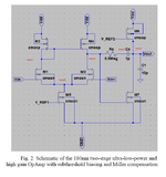
Hello Guys, This is just a very elementary question for you. But for me it is new, I have searched this Subthreshold Op-amp which is a work by Engineers, Sumukh Nitundil, Nihal Singh, R. Balaji, Pankaj Arora. I use this Op-Amp to a Bandgap Reference, Where should I connect the V_REF1 and V_REF2 ? (Since I thought that the only terminal used are the Vin- , Vin+ and Vout.)
The Reference is here https://www.semanticscholar.org/pap...ingh/84117ff2fffab8d8bd3674ddd06032aefea56f8a
The Reference is here https://www.semanticscholar.org/pap...ingh/84117ff2fffab8d8bd3674ddd06032aefea56f8a