Continue to Site

Welcome to EDAboard.com

Welcome to our site! EDAboard.com is an international Electronics Discussion Forum focused on EDA software, circuits, schematics, books, theory, papers, asic, pld, 8051, DSP, Network, RF, Analog Design, PCB, Service Manuals... and a whole lot more! To participate you need to register. Registration is free. Click here to register now.

strange problem pic16f877a

Status
Not open for further replies.

5282604

Full Member level 4
Joined
Dec 19, 2009
Messages
194
Helped
3
Reputation
6
Reaction score
3
Trophy points
1,298
Location
egypt
Activity points
2,404
i use xt 4mhz crystal and i try long time and no solution.
the problem is. i make simple loop. on and off an led with 500ms delay . it work in simulation .
but in my circuit it's take about 10sec to flashing led. :?:
 

Post your code.
what compiler you are using?
And also specify your microcontroller?
 

mikroc pro 4.6
chip pic16f877a
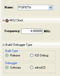
crystal 4mhz xt


void main() {
TRISD=0x00; // TRISD OUTPUT

while(1){
portd=1;
delay_ms(500);
portd=0;
delay_ms(500); }
}


work in simulation . but in my real circuit delay is 10 sec no .5sec
 

I don't know C very well but your code looks OK, my thoughts on this is what about the configuration word? You should ensure that the watchdog timer is off and you could also try HS mode instead of XT mode in the crystal configuration bits.
 

You must turn off analog module and comparator.by adding this code we can turn off these module.
Adcon1=0x07;
Cmcon=0x07;

- - - Updated - - -

void main() {
Adcon1=0x07;
Cmcon=0x07;
TRISD=0x00; // TRISD OUTPUT
while(1){
portd=1;
delay_ms(500);
portd=0;
delay_ms(500); }
}
 

You must turn off analog module and comparator.by adding this code we can turn off these module.
Adcon1=0x07;
Cmcon=0x07;

- - - Updated - - -

void main() {
Adcon1=0x07;
Cmcon=0x07;
TRISD=0x00; // TRISD OUTPUT
while(1){
portd=1;
delay_ms(500);
portd=0;
delay_ms(500); }
}

i try this code and the problem is still.

- - - Updated - - -

I don't know C very well but your code looks OK, my thoughts on this is what about the configuration word? You should ensure that the watchdog timer is off and you could also try HS mode instead of XT mode in the crystal configuration bits.

yes i do this
 

i use xt 4mhz crystal and i try long time and no solution.
the problem is. i make simple loop. on and off an led with 500ms delay . it work in simulation .
but in my circuit it's take about 10sec to flashing led. :?:

most likely problem is that you think you are using 4mhz, but actually clock is not 4mhz. PIC has many clocking modes, and you have to do all the settings to make sure it is using external crystal and not (for example) internal RC mode
 

The "delay_ms()" function is a software generated delay and as such it needs to know how many instructions to loop through to generate the required time. Check you have a line in your code, somewhere near the top or a configuration setting somewhere to tell it that the clock is 4MHz. If it assumes a different clock frequency is being used the delay will be wrong.

Brian.
 

post the full code

tell us which is the compiler you are using

and also post the your circuit
 

check crystal in board.
 

#7
i set clock in mikroc at 4mhz.

#8
yes delay_ms is software generated delay.

#9
post code in post 5# , i use simple circuit pic + reser resistor + crystal and 2 cap i try 22p and 15p and no capictor and problem still

#10
i try 3crystal and problem is still.

-------------------------------------------

- - - Updated - - -

1.png
2.png
 

post your actual circuit

most likely problem is that you think you are using 4mhz, but actually clock is not 4mhz. PIC has many clocking modes, and you have to do all the settings to make sure it is using external crystal and not (for example) internal RC mode
 

**broken link removed**

i use this circuit but without diode and i use 4mhz crystal.


when i remove 4mhz crystal from my circuit the pic16f877a is work but slow" see post 1# " . it's means pic16f877a clocked by internal osc.
 

Hi,

The 16F877A does not have any internal oscillators, only external ones.

If the led is flashing very slowly with the crystal removed, its just by chance / random oscillations.

How have you built your circuit, on a pcb, hand wired or on a breadboard ?

How far from the chip is the crystal ? - it should be as close a possible.

Have you got boths sets of power rails connected ? pins 11 and 12, and 31 and 32.

Have you got a 100nf cap across pins 11 and 12 ?


What are you using for a power supply ?


A picture would help ..
 

how many pic microcontroller you are using................

change the pic microcontroller and see, i mean the microcontroller which u are using may be got damaged.................

otherwise first check whether your pic miicrocontroller working fine or not..........
 

If the crystal is removed and the circuit still works albeit very slowly, it means that the configuration bits for the oscillator are set for RC mode not XT or HS mode.
 

Hi,

The 16F877A does not have any internal oscillators, only external ones.

If the led is flashing very slowly with the crystal removed, its just by chance / random oscillations.

good catch wp100. though i noted that '877A does have an internal RC osc for the watchdog, and there's some mention of an internal RC osc for the ADC ?
with crystal removed, there should ideally be no random oscillations - why would there be ?

so here is a theory --
the watchdog is not disabled, but there is also no Fosc with crystal removed. hence the WD keeps activating the mcu and makes it step through the code very slowly ?

maybe OP should check if his crystal is operating at 4Mhz or not, and all settings for this are properly set. if only he has an oscilloscope ??
 

The watchdog causes a reset so it can't step through the code. If the power pins are not all connected and the decoupling capacitors are missing it is possible the crystal oscillator is not running in fundamental mode or is randomly pulsing.
The WDT and ADC internal RC clocks can't be used to drive the PCLATH/PCL so it isn't possible they are the problem.
We need a FULL schematic to give a better diagnosis, the one provided doesn't even show the errant LED!

Brian.
 

We need a FULL schematic to give a better diagnosis, the one provided doesn't even show the errant LED!

Brian.

well said !! without better inputs, it is useless trying to help
 

Status
Not open for further replies.

Similar threads

Part and Inventory Search

Welcome to EDABoard.com

Sponsor

Back
Top