Continue to Site

Welcome to EDAboard.com

Welcome to our site! EDAboard.com is an international Electronics Discussion Forum focused on EDA software, circuits, schematics, books, theory, papers, asic, pld, 8051, DSP, Network, RF, Analog Design, PCB, Service Manuals... and a whole lot more! To participate you need to register. Registration is free. Click here to register now.

Strange behavior of Closed Loop Full differential Amplifier

Status
Not open for further replies.

Ali263

Member level 1
Joined
Aug 21, 2020
Messages
40
Helped
0
Reputation
0
Reaction score
1
Trophy points
6
Activity points
450
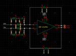
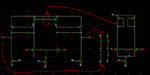
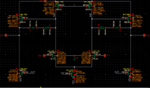
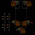
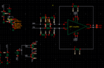
I am designing a fully differential amplifier, Two stage amplifier, with a common mode feedback network ,Single stage Differential Amplifier, with Active Load.

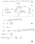
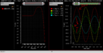
When i connect the amplifier in close loop I expect Dc gain to be set by R2/R1 , R2 is feedback resistor and R1 is input resistor but when I do simulations i get a dc gain of -2db for R2/R1=1
 

Attachments

  • 2.PNG
    2.PNG
    22.8 KB · Views: 188
  • 1.PNG
    1.PNG
    30.2 KB · Views: 149

Moved to analog IC forum.

Nothing strange. The closed loop gain would be exactly equal to R2/R1 only for infinite amplifier open loop gain. -2 dB suggests too low amplifier gain respectively to high output impedance.
 

    Ali263

    Points: 2
    Helpful Answer Positive Rating
@FvM but my open loop gain DC gain is 42dB isn't that enough.
Does the CMFB Network effect the closed loop gain?
 

Can you check your DC operating point in closed loop and let us know what you get? Do you see the amplifier outputs/inputs snap to one of the supply rails? What is the value of yout common-mode sensing resistors?
 

@sutapanaki the DC point for closed loop is 598mv. I think that's ok.

Can you tell me or recommend me something about sizing of resistor in sensing network and its effect on gain OL/CL?
 

Begin with whether the loop is in fact closed.
If the two inputs show a significant difference
voltage then you're probably not anywhere
near peak gain.

Then check that CMFB has positioned the
(outp+outn)/2 at about (VDD+VSS)/2, as
gross common mode deflection can also
ruin gain. 598mV would be sane for 1.3V
(VDD-VSS) but not really, for (say) 2.5V
or 0.8V.

Then, check whether your op amp's output
drive is capable of sourcing / sinking the
feedback networks' required current. It
looks like a simple current mirror on the
low side, which might well come up short.

Do not forget about input common
mode range. The simple NMOS input might
well be choked off if the two input sources
are ground referred, rather than (VDD+VSS)/2
(same as output common mode ref?).
 
Last edited:

Check the loop-gain instead of open-loop gain to see the effect of the biasing network on the transfer function.

You can do that by using cmdm probe between the amplifier output and the feedback resistors.
 

You want to choose the feedback sensing resistors such that they don't kill your gain because differentially, they appear as loads to the second stage. Since you expect a gain of 1, or 0dB and you get something like -2dB (or about 0.8), this could be a possible reason or part of the reason. Another part for gain reduction can come from the finite DC gain of the OTA itself.

When I asked for the operating point information I meant for you to show on the schematic annotated values of voltages and currents and gm of the devices.
Dear,

Kindly see the snaps with all values annotated.
 

Attachments

  • 1.PNG
    1.PNG
    62.9 KB · Views: 114
  • 2.PNG
    2.PNG
    37.9 KB · Views: 126
  • 3.PNG
    3.PNG
    41.1 KB · Views: 125
  • 4.PNG
    4.PNG
    158.4 KB · Views: 144

Check the loop-gain instead of open-loop gain to see the effect of the biasing network on the transfer function.

You can do that by using cmdm probe between the amplifier output and the feedback resistors.

Thankyou very much for this idea. It seems to be a good approach but seeing my circuit of 2 stage amplifier and cmfb where exactly should i insert the probe since documents say insert the probe where it break all loops.

Thank you
 

Hi Ali,

By placing the cmdm probe as I described, you will only be able to check for the differential loop-gain.
If you are also interested in the cmfb stability, you should place the cmdm probe between the output of the amplifier and the input of the cmfb. With this, you break the two (cm/dm) loops.

Regards.
 

    Ali263

    Points: 2
    Helpful Answer Positive Rating
What is the value of your common-mode sensing resistors?

I was left with the impression from your first post that you wanted a close loop gain of 0dB. Instead, I see it is -6db. What is your target? Added to that, what are the values of the resistors in the feedback of the amplifier? and the capacitor too?
 

    Ali263

    Points: 2
    Helpful Answer Positive Rating
I tried for 2.5
What is the value of your common-mode sensing resistors?

I was left with the impression from your first post that you wanted a close loop gain of 0dB. Instead, I see it is -6db. What is your target? Added to that, what are the values of the resistors in the feedback of the amplifier? and the capacitor too?

i tried for 12.5k and 25k sensing resistors.
First, I designed single ended differential amplifier and it gives me 0dB dc gain for Rf/Ri=1.
But now when I am trying with fully differential my close loop dc gain falls to 0 dB for Rf/Ri=1

Rf=Ri=9.774K
Ci=11.24pF

Target is dc Gain of 0 dB for Rf/Ri=1
 

From your operating point and resistor values (12.5K for CMFB resistors) your loop gain (assuming stable CMFB loop) is in the order of 133.6V/V or 42.5dB. With equal feedback resistors your closed loop DC gain should be 0.99 or -0.065dB. From the transient plots you showed and if I read them correctly, looks like you have a gain of 2, not 0.5. I might not be reading them correctly because it is not very clear but from your annotations on the plot it looks like output is 2x higher than input. This doesn't correspond to the -6dB from the ac response, nor does it correspond to the calculated closed loop gain of almost 1. Also, from your ac plot the gain goes up to 0dB after 1MHz or so. This is happening when the capacitor in the impedance connected to the inputs of the amplifier is effectively short with respect to the resistor in series with the capacitor and so, your input resistance is the parallel combination of R14 and R15. This indicates that when this happens R15||R14 becomes equal to the feedback resistor and you get a gain of 1. This means that each of the R14 and R15are 2x higher than the feedback resistor, resulting in DC gain of -6dB. Is it like that or maybe the way you measure your gain is not correct. If you only do the differential loop gain what do you get?
 
  • Like
Reactions: Ali263

    Ali263

    Points: 2
    Helpful Answer Positive Rating
From your operating point and resistor values (12.5K for CMFB resistors) your loop gain (assuming stable CMFB loop) is in the order of 133.6V/V or 42.5dB. With equal feedback resistors your closed loop DC gain should be 0.99 or -0.065dB. From the transient plots you showed and if I read them correctly, looks like you have a gain of 2, not 0.5. I might not be reading them correctly because it is not very clear but from your annotations on the plot it looks like output is 2x higher than input. This doesn't correspond to the -6dB from the ac response, nor does it correspond to the calculated closed loop gain of almost 1. Also, from your ac plot the gain goes up to 0dB after 1MHz or so. This is happening when the capacitor in the impedance connected to the inputs of the amplifier is effectively short with respect to the resistor in series with the capacitor and so, your input resistance is the parallel combination of R14 and R15. This indicates that when this happens R15||R14 becomes equal to the feedback resistor and you get a gain of 1. This means that each of the R14 and R15are 2x higher than the feedback resistor, resulting in DC gain of -6dB. Is it like that or maybe the way you measure your gain is not correct. If you only do the differential loop gain what do you get?

I am really impressed and like the way you respond timely and with details. I am still working on it. I have found the value of sensing resistors is having its effect and it is because of that(as per my analysis, not final yet) . I am working right now on it and will update ASAP.
You have my respect boss :)

Kindly, Tell me one thing, how you calculated the loop gain from operation point value and resistor values?
--- Updated ---

I am really impressed and like the way you respond timely and with details. I am still working on it. I have found the value of sensing resistors is having its effect and it is because of that(as per my analysis, not final yet) . I am working right now on it and will update ASAP.
You have my respect boss :)

Kindly, Tell me one thing, how you calculated the loop gain from operation point value and resistor values?

Also please what exactly is meant by STABLE CMFB? I want to confirm this point too
--- Updated ---

I am really impressed and like the way you respond timely and with details. I am still working on it. I have found the value of sensing resistors is having its effect and it is because of that(as per my analysis, not final yet) . I am working right now on it and will update ASAP.
You have my respect boss :)

Kindly, Tell me one thing, how you calculated the loop gain from operation point value and resistor values?
--- Updated ---
OK, so if i increase sensing resistors Values , Open loop gain increases but close loop gain decreases and if i decrease sensing resistor values open loop gai increases but close loop gain decreases.

Now this is something very strange to me
 
Last edited:

That really makes no sense. If your open loop gain increases, that is you loop gain becomes bigger, it should not affect your closed loop gain. After all that's what we want - we want high loop gain, so that the closed loop gain is only defined by the external feedback network. If you don't touch the external resistors then the closed loop gain shouldn't change almost at all.
By stable CMFB loop I mean that this loop is not oscillating and is regulating the output common mode in a stable way.
--- Updated ---

For the loop gain
 

Attachments

  • Capture.PNG
    Capture.PNG
    88 KB · Views: 114
  • Like
Reactions: Ali263

    Ali263

    Points: 2
    Helpful Answer Positive Rating
From your operating point and resistor values (12.5K for CMFB resistors) your loop gain (assuming stable CMFB loop) is in the order of 133.6V/V or 42.5dB. With equal feedback resistors your closed loop DC gain should be 0.99 or -0.065dB. From the transient plots you showed and if I read them correctly, looks like you have a gain of 2, not 0.5. I might not be reading them correctly because it is not very clear but from your annotations on the plot it looks like output is 2x higher than input. This doesn't correspond to the -6dB from the ac response, nor does it correspond to the calculated closed loop gain of almost 1. Also, from your ac plot the gain goes up to 0dB after 1MHz or so. This is happening when the capacitor in the impedance connected to the inputs of the amplifier is effectively short with respect to the resistor in series with the capacitor and so, your input resistance is the parallel combination of R14 and R15. This indicates that when this happens R15||R14 becomes equal to the feedback resistor and you get a gain of 1. This means that each of the R14 and R15are 2x higher than the feedback resistor, resulting in DC gain of -6dB. Is it like that or maybe the way you measure your gain is not correct. If you only do the differential loop gain what do you get?
"From your operating point and resistor values (12.5K for CMFB resistors) your loop gain (assuming stable CMFB loop) is in the order of 133.6V/V or 42.5dB."
How did you find this ? Please can you say it.


Thanks alot
 

I am too lazy to read whole discussion.
What is you ac analysis setup and gain expression measurement?
For me it looks like "invalid user" case (in testbench not circuit)
 

Status
Not open for further replies.

Part and Inventory Search

Welcome to EDABoard.com

Sponsor

Back
Top