Continue to Site

Welcome to EDAboard.com

Welcome to our site! EDAboard.com is an international Electronics Discussion Forum focused on EDA software, circuits, schematics, books, theory, papers, asic, pld, 8051, DSP, Network, RF, Analog Design, PCB, Service Manuals... and a whole lot more! To participate you need to register. Registration is free. Click here to register now.

Steps to Load pull, Stabilize and Match a power amplifier

Status
Not open for further replies.

ge

Full Member level 5
Joined
Jun 23, 2006
Messages
250
Helped
29
Reputation
58
Reaction score
29
Trophy points
1,308
Location
Pennsylvania, USA
Activity points
2,772
I did an IV curve…
IV Setup.png


IV Sim.png

-2.2V gate voltage looks about Class A.


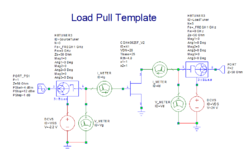
In AWR, I then run a Load Pull and Source Pull to find the impedances I need to match to.
LP Template.png


LP Plot.png


I then would run Network Synthsis that pulls from the LP Tuners to derive a matching network.
Without out the 5 ohm stabilization resistor on the gate, I get error messages from AWR.

Obviously a resistor is not going to be the first device on the input matching network but will likely be somewhere in the matching network…

How do I take into account the stabilization resistor ?
 

Remove stabilization resistor and re-do Load Pull simulation and find the LPs values.
Then remove manually 5 Ohm (not normalized) from the real part of the Source Pull Impedance and apply these new values to another simulation set-up.
 

Remove stabilization resistor and re-do Load Pull simulation and find the LPs values.
Then remove manually 5 Ohm (not normalized) from the real part of the Source Pull Impedance and apply these new values to another simulation set-up.
Appreciate the reply BigBoss,


>> Remove stabilization resistor and re-do Load Pull simulation and find the LPs values.
When I remove the stabilization resistor, I get error messages of
I'm unsure how to "Then remove manually 5 Ohm (not normalized) from the real part ...". I understand 5 ohms is real, not imaginary, but how do I do this in AWR? I'm digging thru the AWR LP data file now.
Remove stabilization resistor and re-do Load Pull simulation and find the LPs values.
Then remove manually 5 Ohm (not normalized) from the real part of the Source Pull Impedance and apply these new values to another simulation set-up.
Oh, are you saying to put 5 ohms in Mag1 of the HPTuner?
--- Updated ---

Remove stabilization resistor and re-do Load Pull simulation and find the LPs values.
Then remove manually 5 Ohm (not normalized) from the real part of the Source Pull Impedance and apply these new values to another simulation set-up.
I'm still not getting it.
 
Last edited:

Remove stabilization resistor and re-do Load Pull simulation and find the LPs values.
Then remove manually 5 Ohm (not normalized) from the real part of the Source Pull Impedance and apply these new values to another simulation set-up.
Please explain how I manually remove resistor.
 

Please explain how I manually remove resistor.
The default Load Pull Template of AWR has no resistors at all in it. You inserted that resistor into it manually and therefore AWR gives you this error because you have modified the netlist.
All I'm just saying that remove this resistor from the original template and use the template as normal/default.
Find the Source and Load Optimum Impedances for your target and then extract 5 Ohm value from the Real Part of Source Pull and create another setup to find the difference. What and how it will impact on the stability if it indeed has an impact.
Don't worry, the Load Pull will not be affected from stability issues. The optimum values which will be found after simulation will also the right values.
 

The reason I put in a resistor on the gate is because the simulator gives an HB error without it. Looking at stability circles shows the points not converging to be outside the smith card. The Load Pull simulation is affected by stability issues. HB does not converge to an answer.
--- Updated ---

The default Load Pull Template of AWR has no resistors at all in it. You inserted that resistor into it manually and therefore AWR gives you this error because you have modified the netlist.
All I'm just saying that remove this resistor from the original template and use the template as normal/default.
Find the Source and Load Optimum Impedances for your target and then extract 5 Ohm value from the Real Part of Source Pull and create another setup to find the difference. What and how it will impact on the stability if it indeed has an impact.
Don't worry, the Load Pull will not be affected from stability issues. The optimum values which will be found after simulation will also the right values.
In the YouTube video Design Example: RF Power Amplifier (PA) with Load-pull on the AWR Design Environment channel, 2:42, 5:55, 7:18, etc Ivan Boshnikov shows stabilization resistor to allow simulation to function. He does not go into detail of how to remove the RC in his simulaiton. I don’t know if edaboard allows hyperlink.
 
Last edited:

I have tried to quickly implement your Load Pull set-up in AWR by using Cree's latest Design Kit and I didn't see any convergence issue at all. You may need to change the DK.
 

With Tuners set to zero, Frequency: 0.05, 0.5, 1 GHz.
the attached has Tuners set to Fine, which is a bit excessive.
I save Load Pulls to separate data files LP_Data & SP_Data.
Project files attached. If you want to run, you will need to replace/reload CREE Process Library and replace CREE Fet. It seems not to make the trip. I'm running CREE_Wlfspd Library version 0.0.2.3.
I am running AWR v16.03. My company is a pain but will be updating in the next week or two.
LP Template.png

AWR v16, Error message shows up in status window. Note that error messages clear at end of simulation but shows up in status window. See ErrorMessage.txt
Simulation Window.png

--- Updated ---

I have tried to quickly implement your Load Pull set-up in AWR by using Cree's latest Design Kit and I didn't see any convergence issue at all. You may need to change the DK.
Ok, I see emp and vin project files did not get attached. I'll try zip.
 

Attachments

  • LP Template.png
    LP Template.png
    32.6 KB · Views: 85
  • EDABoard.zip
    3.9 MB · Views: 79

I just have seen Vgs voltage is -2.2V that is huge for Idq. Cree used 250mA for nominal operation.
The convergence error may come from.
I have used -2.85V for 250 mA Idq and everything is fine. I think Load Line is not really correct.
 

I suspect CREE is running -2.85v for Class AB to Class B. I'm running Class A to Class AB, closer to Class A. My IV curves is at the beginning of this email. If I run a line from 40V to 3A, it would be roughly -2.2v to -2.3v. I'll play around with Gate bias. Maybe I can get the simulation to run with something close to Class AB.
 

Status
Not open for further replies.

Part and Inventory Search

Welcome to EDABoard.com

Sponsor

Back
Top