monolothics
Junior Member level 3
Hi..
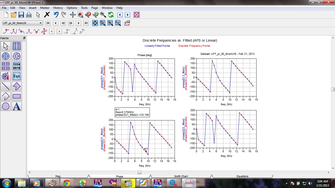
i'm currently designing LPF using stepped impedance that operate at 9.4 GHz and also i want my LPF have constant 90° phase shift at 9.4 GHz
so after i have the L-C value, i transform it to microstrip with
dielectric constant (εr) = 2.33
dielectric thickness (h) = 0.787 mm
and
Zlow = 10 Ω
Zhi = 110 Ω
so when i simulate it using schematic in ADS i get very good output,
but when i simulate it in ADS layout using microwave simulation i can't get the exact result like the one i simulate using schematic
anyone has an idea??
here's a picture