Continue to Site

Welcome to EDAboard.com

Welcome to our site! EDAboard.com is an international Electronics Discussion Forum focused on EDA software, circuits, schematics, books, theory, papers, asic, pld, 8051, DSP, Network, RF, Analog Design, PCB, Service Manuals... and a whole lot more! To participate you need to register. Registration is free. Click here to register now.

Step up transformer : Comparing ratio of currents to ratio of inverse of turns

Status
Not open for further replies.

powerengineer

Newbie level 1
Joined
Jan 23, 2012
Messages
1
Helped
0
Reputation
0
Reaction score
0
Trophy points
1,281
Activity points
1,293
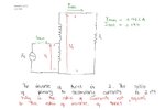
I have attached the diagram of the autotransformer and also labelled the currents so that you guys can better understand my question. The question is why is the ratio of the primary and secondary winding currents slightly different to the ratio of the inverse of turns when ideally they should be equal.
Capture.JPG

Attempt to solution :


The ratio of the current in the primary and secondary winding is not slightly different that the ratio of the inverse of turns because of the magnetizing current. Even after the voltage at the primary winding is brought to zero, there will still be some current in the secondary core because it will still be magnetized.
 

With transformers/autoformers we expect a certain amount of lost power due to inefficiencies.

Your schematic appears to have losses of 19%. It sounds a bit high to me, although there could be a detail or two that I missed.
 

Hello powerengineer.
Of course in ideal condition there is no difference in current ratio and inverse of the turn ratio,but practically is not the case .In practical condition the transformer working follows according to the formula as mentioned below:-
IpVp-(cu and iron losses)=IsVs. Regards
 

Hi !
can you please tell me with what program you have drawn your attached circuit diagram?
thanks !
 

The answer is that there is extra magnetising current flowing in the primary winding, supplied by the source, if the transformer was ideal, Lmag = infinity, I mag = 0 and the current x turns would match exactly, Regards, Orson Cart.

p.s. note that all of Iprim does not flow in the lower winding, for an ideal auto-transformer with equal turns, the currents will be the same, for a 1:2 turns ratio the current will be 2:1.
 
Last edited:
Status
Not open for further replies.

Similar threads

Part and Inventory Search

Welcome to EDABoard.com

Sponsor

Back
Top