Continue to Site

Welcome to EDAboard.com

Welcome to our site! EDAboard.com is an international Electronics Discussion Forum focused on EDA software, circuits, schematics, books, theory, papers, asic, pld, 8051, DSP, Network, RF, Analog Design, PCB, Service Manuals... and a whole lot more! To participate you need to register. Registration is free. Click here to register now.

State machine on PIC ?

Status
Not open for further replies.

bianchi77

Advanced Member level 4
Joined
Jun 11, 2009
Messages
1,313
Helped
21
Reputation
44
Reaction score
20
Trophy points
1,318
Location
California
Visit site
Activity points
9,442
Hello guys,
Does anyone of you know the information about state machine for PIC using assembly ?
Any clues or links will be appreciated ,

Thanks
 

You can make something like a "switch" of language C using assembly.

Code:
functionLabel
movlw high($)
movwf PCLATH
movf stateReg,W
addwf PCL,f

goto state1
goto state2
goto state3
goto state4
;...
;...

state1
;some code here
return

state2
;some code here
return


You can have a variable (stateReg) which contains the state you wanna go. PCL is the low part of the Program counter. When you add stateReg's content to PCL, you will offset the program execution by its content. The next program lines are branches. So, the number stored in stateReg will choose which branch will you take.

The initial sequence 'movlw high($)' and 'movwf PCLATH' is needed because the Program Counter have at least two parts: PCL and PCH. You can't change de PC writing to PCH, but you can do it writing to PCL. And, when you write to PCL, PCH takes the value stores in is latch, PCLATH. So, let's say you are running in the 0x0203 program position, the value of PCLATH is zero, and you are about to add something to PCL, let's say, the value 0x04. You expect go to the 0x0207 position, but the MCU will actually branch to 0x0007 (high part of the program counter takes the value in PCLATH, that was zero!)

This code may be the actual code for PIC16, but in the PIC18 the program counter counts two by two. So, before adding to PCL, you need to multiply the stateReg value by two (just a simple left shift without carry operation).
 

so I can write like this :

Code:
MAIN
movlw 0x04
movwf PCLATH
movf stateReg,W
addwf PCL,f

goto state1
goto state2
goto state3
goto state4
;...
;...

state1
;some code here
return

state2
;some code here
return

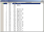
How can I know my program position ?
Like this one ?
program position.jpg
 

It will work only if your "MAIN" is located at the adress 0x0400.

You can set a fixed adress position for a routine using the "org" statement.

Instead of using a fixed value into PCLATH (0x04, as you did) I think it is more safe if you use the parameter "$". It is a literal that contais the adress of the line. Using "high($)" you'll get just the high part of the PC. So, no matter where you put your code (using "org"), PCLATH will be automaticaly set to the proper value.

Code:
org 0x0000

main
call state_machine
goto main


org 0x1000
state_machine
movlw high($)
movwf PCLATH
movf   stateReg,W
addwf PCL,f

goto state1
goto state2
goto state3
goto state4
;...
;...

state1
;some code here
return

state2
;some code here
return
 
  • Like
Reactions: PA3040

    PA3040

    Points: 2
    Helpful Answer Positive Rating
W is the 'work register'. Is equivalent to the 'accumulator' in other architectures.
 

I got error :

Code:
MPLINK 4.42, Linker
Device Database Version 1.7
Copyright (c) 1998-2011 Microchip Technology Inc.
Error - section '.org_2' can not fit the absolute section. Section '.org_2' start=0x00001000, length=0x00000072
Errors    : 1

I have :
Code:
org 0x0000 ;line 1
;The following lines accommodate bootloader
	goto START ;line 1 ($0000)
;Interrupt Handler
	org 0x0004 ;Interrupt Vector
	;incf COUNT ;increase COUNT
	bcf INTCON, T0IF ;clear the overflow flag
	retfie ;return from Interrupt
	
	;org 0x0005

START
.
.
.
.
;main loop begin      
		MAIN
		call state_machine
		goto MAIN
 ;main loop end
 ;==================
		org 0x1000
state_machine
		movlw high($)
		movwf PCLATH
		movf   stateReg,W
		addwf PCL,f
,
,
,


Where should I put "org" for state machine ?
thanks
 

The 'org' for the state machine is correct. But the value 0x1000 was an example. That error indicates that the compiler could not put the code in the program memory range. Probably your PIC MCU have less memory than 0x1000. Which device it is exactly?
 

The 'org' for the state machine is correct. But the value 0x1000 was an example. That error indicates that the compiler could not put the code in the program memory range. Probably your PIC MCU have less memory than 0x1000. Which device it is exactly?
so any suggestion to put that org for state machine ? must be less than 4096 words, isn't it ?
it's 16F658A
my flash memory :
PIC16F648A 4096 words
 

I suggest you to see the device datasheet. There's a section 'Program Memory', inside 'Memory organization'. There you will find in details how much memory you have available. There's also a graph showing the memory organization. It's very easy.
 

Exactly. The graph on the left show you the actual memory limit for your device. I suggest you to first write the full routines, and only after that choose their positions. You need to know their size to know where to put them.
 

Exactly. The graph on the left show you the actual memory limit for your device. I suggest you to first write the full routines, and only after that choose their positions. You need to know their size to know where to put them.
any links for example ? I want to blink LED with task,
thanks
 

The instructions below the line "addwf PCL,f" will make you go to the state defined by stateReg. For example, if you want to go to "state1", how much you need add to PCL? Take into account that when an instruction is being executed, the Program Counter points to the next line. In this case, when the "add" line is being executed, the PC is pointing to "goto state1". So, how much needs to be added to PCL for the instruction "goto state1" be executed? The answer is "zero". When the content of "stateReg" is zero, you'll jump to state1. Following this logic, when stateReg is 0x01, you go state2. When stateReg is 0x02, you go to state3, and so on.

I'll show an example of a simple use of this method. This code reads a push-button switch and eliminate the antibounce effects:

Code:
org 0x0000

movlw 0x00
movwf stateReg

mainloop

call buttonStateMachine

btfss flag
bcf LED
btfsc flag
bsf LED

goto mainloop


buttonStateMachine
movlw high($)
movwf PCLATH
movf   stateReg,W
addwf PCL,f

goto readButton
goto waitAntibounce
goto waitRelease

readButton
btfss BUTTON
return
movlw 100
movwf timerAntibounce
movlw 0x01
movwf stateReg
return

waitAntibounce
movf timerAntibounce,f
btfss STATUS,Z
return
btfss BUTTON
goto button_not_pressed_anymore
button_still_pressed
bsf   flag
movlw 0x02
movwf stateReg
return

button_not_pressed_anymore
bcf   flag
clrf stateReg
return

waitRelease
btfss BUTTON
clrf stateReg
return

You see, this is code is not complete. I didn't write the timer routines. The register "timerAntibounce" will be decremented each 1ms.

The essence is when you are inside the state "readButton", stateReg will not change until something happen (button pressed). When the button pressed, the state is changed to 0x01, and another logic is done inside that state.
 

what's
Code:
btfss flag
for ? how can I define flag ?

- - - Updated - - -

Code:
btfss BUTTON
?
thanks
 

Defining a flag in RAM:

registerOfFlags equ 0x20 ; or some other ram position
#define flag registerOfFlags,0 ; or some other bit (from 0 to 7)


Naming a pin:
#define BUTTON PORTB,RB0 ; or any other pin
 

I tried to blink the LED with state machine but it's only on never off,

What do I miss here ?

Thanks

Code:
CBLOCK 0x20 ; RAM AREA for USE at address 20h
	; Variables used in delay routine
	Kount100us
	Kount1ms
	Kount100ms
	Kount1000ms
    Kount3000ms
    ;Variables
    COUNT
	stateReg
	flag
ENDC

	org 0x0000 ;line 1
;The following lines accommodate bootloader
	goto START ;line 1 ($0000)
;Interrupt Handler
	org 0x0004 ;Interrupt Vector
	;incf COUNT ;increase COUNT
	bcf INTCON, T0IF ;clear the overflow flag
	retfie ;return from Interrupt
	
	;org 0x0005

START  
		;clrf COUNT ;starting from COUNT=0
		banksel INTCON
		bsf INTCON, GIE ;Global Interrupt Enable
		bsf INTCON, T0IE ;tmr0 interrupt enabled
		;clrf TMR0
;=======================================         
        ;init OPTION_REG begin
        ;
		;Timer mode is selected by clearing the T0CS bit
	    ;(OPTION<5>). In Timer mode, the TMR0 register value
		;will increment every instruction cycle (without
		;prescaler). If the TMR0 register is written to, the
		;increment is inhibited for the following two cycles. The
		;user can work around this by writing an adjusted value
		;to the TMR0 register
		;
		;Clearing the PSA bit will assign the
		;prescaler to Timer0. The prescaler is not readable or
		;writable. When the prescaler is assigned to the Timer0
		;module, prescale value of 1:2, 1:4,..., 1:256 are
		;selectable.
		;
        ;set prescaler for timer0 1:256
		;OPTION_REGISTER Configuration based on Page 47 16F648A datasheet
		; RBPU | INTEDG	| T0CS | T0SE | PSA	| PS2 |	PS1	| PS0 
		;  0   |  0	    | 	0  |   0  |  0	|  1  |	 1	|  1 
		
		
		banksel OPTION_REG
		;movlw b'00000111'
		movlw 0x07
         movwf OPTION_REG
		;init OPTION_REG end
;=======================================         
        ;init PORTA begin
  		banksel TRISA
 		movlw   PORTA_IO ;set PORTA input and output, all are output
		movwf   TRISA   
        ;init PORTA end
;=======================================                 
        ;init PORTB begin
		banksel TRISB
 		movlw   PORTB_IO ;set PORTB input and output
		movwf   TRISB
        ;init PORTB end   

;=======================================         
;Create state machine for those LED flashers
;=======================================
MAIN
	call STATE_MACHINE
    ;call delay1ms
	goto MAIN
;end of main
;=======================================
;init state machine on address 0x0019
; RAM to bookmark current location in each state.

	org 0x0019
STATE_MACHINE
	;how to switch between state ?  
    movf  stateReg,w  ;state bits ( check bit flag )
    ;addwf PCL,f
    addwf PCL

;===init LED PORT before calling state machine begin		
 		banksel TRISB
		;flash LED on PORT RB4
		bcf     TRISB, LED 		;PORTB<4> as output RB4
		banksel	PORTB 	   		;now we are on PORTB 
;===init LED PORT before calling state machine end
;====do the state begin
		goto state1   ;LED on State
		
		goto state2   ;LED off State
		
		goto state3   ;LED on State
		
		goto state4	  ;LED off State 	
		
		goto state5   ;LED on State
		
		goto state6   ;LED off State

;===do the state end
             
;=======================================


;AGAIN   

;subroutine delay1s
;
;delay1s
;		banksel COUNT
;		btfss COUNT, 0x06 ;check if COUNT increased to 0x06
		
;		goto delay1s
;int1s 	btfss COUNT, 0x03 ;bit 3
;		goto int1s
;int1s2
;		btfss COUNT, 0x02 ;bit 2
;		goto int1s2
		;now 1 sec expired
;		clrf COUNT ;COUNT=0
;return


;DELAY SUBROUTINE for 161.6uS  delay
;=======================================
delay51uS
		 clrf TMR0 ;Clear TMR0 and prescaler
		 banksel TMR0
		 movlw 0xFF ;Count=FF for 161.6uS to expire, measure from stopwatch simulation
		 movwf TMR0
;over 	 btfss INTCON, T0IF ;Tmr0 overflow?
         btfss INTCON, T0IF ;Tmr0 overflow?
;		 goto over
;		 bcf INTCON, T0IF ;reset/clear when done
over	 decfsz TMR0
         goto over
         bcf INTCON, T0IF ;reset/clear when done
return
;=======================================
;=======================================
;DELAY SUBROUTINE for 1ms  delay
delay1ms
		 
		 movlw 0x06 ;Count=6 for 1ms to expire
		 movwf Kount1ms
R1ms     call delay51uS
		 decfsz Kount1ms ;reduce 100 until it's zero
		 goto R1ms
return
;=======================================
;=======================================
;DELAY SUBROUTINE for 100ms  delay for 1000ms to expire
delay100ms
		 
		 movlw 0x64 ;Count=100 for 100ms to expire
		 movwf Kount100ms
R100ms   call delay1ms
		 decfsz Kount100ms ;reduce 100 until it's zero
		 goto R100ms
return
;=======================================
;=======================================
;DELAY SUBROUTINE for 1000ms  delay for 1000ms to expire
delay1s
	 
		 movlw 0x0A ;Count=10 for 1000ms to expire
		 movwf Kount1000ms
R1000ms   call delay100ms
		 decfsz Kount1000ms ;reduce 100 until it's zero
		 goto R1000ms
return
;=======================================
;=======================================
;DELAY SUBROUTINE for 3000ms  delay
delay3s
		 
		  movlw 0x03 ;Count=3 for 3000ms to expire
		  movwf Kount3000ms
R3000ms   call delay1s
		  decfsz Kount3000ms ;reduce 3 until it's zero
		  goto R3000ms
return
;=======================================


state1 	
		
		bsf     PORTB, LED 		;Turn on LED
		;call 	delay1s    		;Keep on for 1s
		movlw 	0x006			;set Program counter
		movwf 	stateReg        ; to state2 
        return					;return to state machine
state2
        bcf 	PORTB, LED 	   	;Turn off LED
	    ;call 	delay1s    		;Keep off for 1s
		
		movlw 	0x007			;set Program counter
		movwf 	stateReg        ; to state2 
        return					;return to state machine
state3  
		
		bsf     PORTB, LED 		;Turn on LED
		movlw 	0x008			;set Program counter
		movwf 	stateReg        ; to state2 
        return					;return to state machine
	   ;call 	delay1s    		;Keep on for 1s
state4
	    bcf 	PORTB, LED 	   	;Turn off LED
	   ;call 	delay1s    		;Keep off for 1s
		
		movlw 	0x009            ;set Program counter 
		movwf 	stateReg         ;to state3
		return					 ;return to state machine	
		

state5  
		bsf     PORTB, LED 		;Turn on LED
		;call 	delay1s    		;Keep on for 1s
		movlw 	0x00A			;set Program counter
		movwf 	stateReg        ; to state2 
        return					;return to state machine
state6
        bcf 	PORTB, LED 	   	;Turn off LED
	    ;call 	delay1s    		;Keep off for 1s
        
		;call    delay3s         ;Give a long delay for 3 seconds
	    ;goto STATE_MACHINE
		movlw 	0x005           ;set Program counter 
		movwf 	stateReg        ;to state3
		return  				;return to state machine
;	    goto 	AGAIN	        ;Keep on blinking, loop forever


;end of program
END
 

Status
Not open for further replies.

Similar threads

Part and Inventory Search

Welcome to EDABoard.com

Sponsor

Back
Top