Continue to Site

Welcome to EDAboard.com

Welcome to our site! EDAboard.com is an international Electronics Discussion Forum focused on EDA software, circuits, schematics, books, theory, papers, asic, pld, 8051, DSP, Network, RF, Analog Design, PCB, Service Manuals... and a whole lot more! To participate you need to register. Registration is free. Click here to register now.

start up circuit for PTAT current generation

Status
Not open for further replies.

ffsher100

Junior Member level 3
Joined
Jun 16, 2011
Messages
27
Helped
1
Reputation
2
Reaction score
1
Trophy points
1,283
Activity points
1,486
hi all,
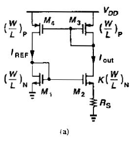
i got PATA current from Razavi at chapter 11.4

there is no more detailed start-up for this circuit.
whether the circuit needn't start-up circuit?
if start-up circuit must have, can anyone recommend or what document i can reference?

thank, in advance.
 

whether the circuit needn't start-up circuit?

It will start up a 1000 times correctly from its own, but it could fail next time, because obviously Vgs of M1 & M2 resp. of M3, M4 & M5 could stay @ 0V , which is a stable condition (you could try with an analysis and such Initial Conditions set). So, yes, it should have a startUp circuit.

You could use the simple startUp circuit from Razavi Sec. 11.3 , Fig. 11.5 (p. 381 in my edition), if the mentioned conditions (below the figure) can be met. If not, but should your (full) circuit generate a general reset pulse anyway during/after starting up the power supply, you could use such a (positive) reset pulse to activate M5 of Fig. 11.5 for a short time to force the startUp.

If all this doesn't apply, use a more complex startUp circuit like, e.g., Razavi Fig. 11.35 (left bottom part) or 11.37 (pp. 400, 401).
 

hi erikl,

there is another question how simulate degenerate point(zero current).
for testing zero current condition, i take Supply-Independent Biasing for example from Razavi
0_1310529307.jpg

my case: ratio of M1,M2 is 10; ratio of M3,M4 is 5 and no startup circuit, the circuit work fine.

how to setup analysis condition to force degenerate point show up?
 

... how to setup analysis condition to force degenerate point show up?
As I told you in my first answer above: use the IC (Initial Condition) statement for the 2 gate nodes.

With the above Supply-Independent Biasing circuit, my simulation result showed correct startUp of the circuit even with the a.m. initial conditions set. So at least this circuit seemingly doesn't need a startUp kick.
 

The trick is, your startup "boot current" must do a couple
of things reliably -

- must push current into a gain node, up to and above the
point where that gain will pull in and lock the current loop.
This gain and minimum boot voltage vary a lot w/ temp,
process and can be subject to "modeling laziness" (very
low current operation often gets inadequate attention,
even if it is consistent enough to model well with enough
effort).

If your gain is high across a very wide current range then
you can boot on leakage / noise. But leakage becomes
small with low temp and clean processing, too small to
be relied upon. Let alone the case where some defect
driven leakage steals "input". You need excess margin.

- the boot current must go elsewhere, before the loop
gets to setpoint. Again the thresholds for this vary w/
environmentals, and subthreshold slope matters a lot
in a CMOS design (tending to not be that well modeled
in "digital" kits).

If you break the bandgap loop and sweep voltage on
your chosen boot-point you can determine the (as
modeled) corners of this box and focus on the worst
cases in tweaking boot circuit design.
 

A easy way for start-up is to use deplete NMOS for M1 and M2.
 

Status
Not open for further replies.

Part and Inventory Search

Welcome to EDABoard.com

Sponsor

Back
Top