Continue to Site

Welcome to EDAboard.com

Welcome to our site! EDAboard.com is an international Electronics Discussion Forum focused on EDA software, circuits, schematics, books, theory, papers, asic, pld, 8051, DSP, Network, RF, Analog Design, PCB, Service Manuals... and a whole lot more! To participate you need to register. Registration is free. Click here to register now.

Stability problem with delta sigma ADC

Status
Not open for further replies.

mordak

Member level 5
Joined
Mar 8, 2013
Messages
82
Helped
0
Reputation
0
Reaction score
0
Trophy points
1,286
Location
Neverland
Activity points
2,134
Hey guys,

I have simulate both discrete and continuous time delta sigma ADCs and came across a weird problem. In continuous time delta sigma, unlike discrete one, stability of the converter depends on the frequency of the input signal. Say there is a low-pass, continuous time, 500kHz delta sigma ADC, (Fs = 32MHz), I expected if I apply 4MHz input signal, I will not be able to reconstruct the signal, since input is far away from the filter bandwidth. But still ADC should work properly without any saturation. However, what I observed was having all integrators in ADC being saturated. I was wondering if I missed anything, or it's a normal phenomenon.
 

Show me STF for both DT and CT Delta Sigma cases.
Is there some peaking for STF of CT case ?
 
Last edited:

Show me STF for both DT and CT Delta Sigma cases.
Is there some peaking for STF of CT case ?

Show me STF for both DT and CT Delta Sigma cases.
Is there some peaking for STF of CT case ?
Thanks for your reply.
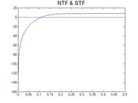
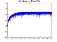
Here is the STF and NTF. This part is based on the theory and H(inf) = 2.5, without optimizing zeros. Actually I don't know if you can get the STF and NTF out of your simulink or not, but I have spectrum of the output for both CT and DT.


Basically for the CT version, I used IIT method to transform the DT to CT. As you can see, both of them are kind of the same. But when I apply a high frequency to both of these ADCs, just in the CT one the output of integrators would go to saturation.
About those peaks that you aksed, actually I don't know how I can see them with simulation, but I've read something about that in some theses, anyway I don't know how these peaks may be the cause of the saturation.
 

Basicall for the CT version, I used IIT method to transform the DT to CT. As you can see, both of them are kind of the same.
You never confirm STF of CT-DSM.

It seems your DSM is a feed forward structure with direct feed forward path since your STF of DT is completely flat.

However STF of CT can't be flat with impulse invariant transformation.

Your STF of CT must have peak in out band.

anyway I don't know how these peaks may be the cause of the saturation.
Peaking of STF cause saturation.
This is well-known defect of FF-CT-DSM.

Again you can never delete peaking of STF of FF-CT-DSM which is over 0dB.

See https://citeseerx.ist.psu.edu/viewdoc/download?doi=10.1.1.69.9775&rep=rep1&type=pdf
 
Last edited:
  • Like
Reactions: mordak

    mordak

    Points: 2
    Helpful Answer Positive Rating
You never confirm STF of CT-DSM.

It seems your DSM is a feed forward structure with direct feed forward path since your STF of DT is completely flat.

However STF of CT can't be flat with impulse invariant transformation.

Your STF of CT must have peak in out band.

Peaking of STF cause saturation.
This is well-known defect of FF-CT-DSM.

Again you can never delete peaking of STF of FF-CT-DSM which is over 0dB.

See https://citeseerx.ist.psu.edu/viewdoc/download?doi=10.1.1.69.9775&rep=rep1&type=pdf
Really good point, thanks. I haven't thought of that before. I am using a third-order CIFF topology. I looked at the paper, it seems they could find a solution to suppress this effect, but you say you cannot delete peaking of STF, I didn't get that.
In my case I am sure there would be some frequencies out of the desired band, so I need to be sure ADC doesn't go to instability. BTW, you mentioned that peaking issues would happen in FF structure, does it mean with FB there would be no problem?
 

I looked at the paper, it seems they could find a solution to suppress this effect, but you say you cannot delete peaking of STF, I didn't get that.
For 3rd order CIFF structure, there are four feed-in coefficients.

I mean if you set only two feed-in coefficients, you can never delete peaking.
This two feed-in coefficient structure is very common for DT-FF-DSM.
I think your CT-FF-DSM must be this only two feed-in structure which is derived from DT-FF-DSM.

If you can set appropriate values for all feed-in coefficients, you can control STF.

does it mean with FB there would be no problem?
Yes.
 
Last edited:

For 3rd order CIFF structure, there are four feed-in coefficients.

I mean if you set only two feed-in coefficients, you can never delete peaking.
This two feed-in coefficient structure is very common for DT-FF-DSM.
I think your CT-FF-DSM must be this only two feed-in structure which is derived from DT-FF-DSM.
I attached the structure I am using for this ADC. b2, b3, g1 are zero. So Feed-in coeff would be a1, a2, a3, b4.
What do you mean by "set only two feed-in coefficients"? what is the "two feed-in structure"? I am using all these coeff when I design the converter.
However, after transforming this structure to the continuous time, another feedback around the internal quantizer would be added to compensate the excess loop delay.


If you can set appropriate values for all feed-in coefficients, you can control STF.
Basically what I am doing is just transforming the DT version to the CT one by that IIT method. You mean I need to find another way to find coeff to prevent peaking?
 
Last edited:

So Feed-in coeff would be a1, a2, a3, b4.
No.
a1,a2,a3 ; Feed-forward Coefficients
b1,b2,b3,b4 ; Feed-in Coefficients

You set b2 and b3 zeros, so your structure is only two feed-in coefficients.

Basically what I am doing is just transforming the DT version to the CT one by that IIT method. You mean I need to find another way to find coeff to prevent peaking.
No.
NTF(z)=1/{1-L1(z)}
STFc(s)=L0c(s)/{1-L1(z)}

You consider only L1(z) and L1c(s).

You have to control L0c(s).
 
  • Like
Reactions: mordak

    mordak

    Points: 2
    Helpful Answer Positive Rating
No.
a1,a2,a3 ; Feed-forward Coefficients
b1,b2,b3,b4 ; Feed-in Coefficients

You set b2 and b3 zeros, so your structure is only two feed-in coefficients.
.
You know I start my design with finding the NTF using Schreier's toolbox and then do the rest of that myself. But after finding the NTF by that toolbox, b2, and b4 would be set to zero in order to realize that transfer function. It's not like I intentionally set the rest of those feed-in coefficients zero.

NTF(z)=1/{1-L1(z)}
STFc(s)=L0c(s)/{1-L1(z)}

You consider only L1(z) and L1c(s).

You have to control L0c(s).

If we assume that loop filter is H(z), so NTF would be 1/(1+H(z)) and STF = H(z)/(1+H(z))
I believe what you wrote was another way of representing the STF and NTF, but considering my representation, I would take care of H(z) and transfer it to CT in a right way, I think. I am a bit confused, do you have any reference that I can read more about what you said.
 

Thanks for the link. Actually I have read it before, not thoroughly, just to get a hang of how this ADC works, and this book mostly describes DT version, I think. Even in a toolbox developed by the author of that book, b2 and b3 would be set to zero, and that was a reason I got a bit confused. I was wondering whether I need not use schreier's toolbox to find NTF or not. Because if I use that toolbox and find the NTF by that, I will have to set b2 and b3 to zero to realize that transfer function, and based on what you said, it seems these two coeff should not be zero if a flat STF is of interest. Please correct me if I was wrong.
 

Actually I have read it before, not thoroughly
Surely read Green Book, especially sections 3.4.2, 4.1, 6.6 and 9.4.

Even in a toolbox developed by the author of that book, b2 and b3 would be set to zero
Not correct.
Schreier's Toolbox does give only b1, it does not give b4.
This only two feed-in coefficients structure is called as "Silva-Steensgaard Structure".

Again surely read Green Book.

I was wondering whether I need not use schreier's toolbox to find NTF or not.
You should use it for finding L1(z), that is, NTF(z).

synthesize_NTF() consider only L1(z), that is, NTF(z).

Because if I use that toolbox and find the NTF by that, I will have to set b2 and b3 to zero to realize that transfer function
You can't understand NTF and STF at all.

L1(z), that is, NTF(z) is determined by feed-back and feed-forward coefficients.

On the other hand, L0(z) is determined by feed-in and feed-forward coefficients.
So STF(z) is determined by feed-in, feed-forward and feed-back coefficients.

realize_NTF() does not give you feed-in coefficients.
It simply set c1=b4=b1.

Although you can realize any frequency characteristic of STF, it is no more than small signal characteristics.

You have to study and control large signal characteristics, that is, stochastic characteristic of output amplitude of integrators.
This task is not so easy.

Again surely read Green Book.
 

Status
Not open for further replies.

Similar threads

Part and Inventory Search

Welcome to EDABoard.com

Sponsor

Back
Top