Continue to Site

Welcome to EDAboard.com

Welcome to our site! EDAboard.com is an international Electronics Discussion Forum focused on EDA software, circuits, schematics, books, theory, papers, asic, pld, 8051, DSP, Network, RF, Analog Design, PCB, Service Manuals... and a whole lot more! To participate you need to register. Registration is free. Click here to register now.

SRD short pulse generator

Status
Not open for further replies.

ttse7

Junior Member level 2
Joined
Mar 7, 2006
Messages
22
Helped
0
Reputation
0
Reaction score
0
Trophy points
1,281
Activity points
1,447
srd pulse generator

Hi all,

This is ttse7 again. Sorry I keep asking the same type of question here. I plan to make a short pulse with 0.5ns pulse width. I follow the HP application note 918 and build with lump elements, the SRD is from M-pulse, MP4023. The final result is that the pulse width is only 40ns. I upload the schematics here. Any expert here can help.

89_1160099028.jpg


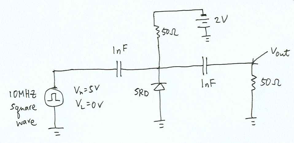
Thanks for your big hand.
 

srd pulse

Hi,

I'm too trying to evulate SRD. I'm still not to mutch expert about it jet but there should be a coil before the diode. the coil should store the energy so when the transiente should appear it will have a lot of energy.

Ran

Added after 8 minutes:


p.s.

the input frequency should be much higher about 100-300 MHz.
 

short pulse generator

I think the output capacitor you used is too large
you can try small capacitors for output
 

srd generator

You do not follow so good, do you?

If you had actually followed the HP ap note, you would have a shunt capacitor at the 10 MHz generator, folllowed by a series inductor, then a shunt capacitor, and finally a series inductor leading up to the SRD.

You also would not have a battery in the circuit, and the 50 ohm bias resistor would be more like 22K ohm.

The last series inductor before the SRD is critical.

Probably need 100 mw OR MORE to drive the diode.
 

comb generator schematic

biff4,

thanks for your comment. I follow the circuit found in HP applicatio note 918. In the circuit I follow, it does not have any inductor. May be I do not fully understand the circuit configuration. It must be something worng but I still wonder which part brings me trouble. Anyway, biff4, I would try what you recommend and understand it fully.

ttse7
 

pulse generator with srd

Sorry, you are right. They DO have that useless circuit shown in AN918.

I am going to suggest that you completely ignore it, as it will not work.

Start off with this paper:

http://www.hp.woodshot.com/hprfhelp/5_downld/lit/diodelit/an984.pdf

On the top page you will see a current waveform that makes a sudden change vs time. This is due to the nature of the diode. A normal diode, like a shottky diode, conducts current only when the diode is forward biased. So if you apply a sine wave input voltage to a schottky diode (mounted in shunt, cathode to ground) you will get a half sinewave output voltage waveform for the positive voltage input, and a zero volt out signal when the input voltage sinewave tries to go negative. In other words, the schottky diode immediately clamps any negative going voltage.

A step recovery diode is specially designed so that it can sometimes conduct current for voltage applied in either direction. The do this by making a PN junction diode, but between the P and N materials, they leave a relatively thick Intrinsicly doped region where electrons can drift around. So if you apply a positive half of a sine wave voltage across that diode, it conducts current like a normal diode. BUT if you apply a negative going half sine wave, the electric field in the diode switches polarity immediately, but there are a boat load of electrons floating around in the I region. As the electric field in the diode gets stronger, it accelerates those electrons back to the annode, but then all of a sudden the last free electron is absorbed at the annode, there are not more electrons in the I region, and the big reverse current suddenly goes to zero and stays there.

Now that in intself is not that interesting. But if you were driving the input sinewave into the diode through a significant inductance, then when the reverse flowing current coming out of the I region suddenly goes to zero, the magnetic field in the inductor collapses and causes a hughe voltage spike to occur. That voltage spike is very short lived, and very high (tens of volts).

So what you need, as a bare minimum, is a step recovery diode driven by a big sine wave voltage source through an appropriately sized chip inductor. That is a good start.

The other elements in an actual comb/impulse generator are there to do an input match. Look for comb generator or impulse generator papers, like this one. Unfortunately, al lot of the early papers seem to now be locked up at the IEEE Iexplore site, were you need a membership to read them!

Also, be aware that the diode characteristics have a lot to do with the pulse shape, like diode capacitance, carrier lifetime, transiston time.


http://www.medphys.ucl.ac.uk/resear.../phd/chapter5.pdf#search="srd comb generator"

**broken link removed**

And here is the ONLY decent copy of the type of circuit you should really be using for the input to SRD impulse generator. Unfortunately the output part of this circuit was designed as a freqeuncy multiplier (one output frequency only, so their circuit is a bandpass). You want to ignore the output matching network and output filter and just put a DC blocking capacitor in series to the right of the SRD:

**broken link removed**
 

hp an984

You are going to make a pulse,right?
But as far as I know, the schematic you uploaded here is used for accelerating the rising or falling edge of a "slow" pulse, but not for generating a "pulse".
The pulse driver generates 10MHz square wave,so the pulse duaration time Ps is close to 50ns, the carrier lifetime of MP4023, t is about 15ns, 50-15=35ns, which is approximatly the 40ns result as you see. And the waveform should be with a "fast" rising edge (1ns or less)and a "normal" falling edge(5-10ns according to the 10MHz driver).
By adding a shunt transmission line ,or differential network behind the block capacitor should be okay to change the fast edge into a narrow pulse. For the bias part, the resistor 50ohm here is a bit smaller I think.
Hope that will help
 

srd pulser

HP App Note 920 may be somewhat helpful. If you haven't seen it, look here:
 

Status
Not open for further replies.

Part and Inventory Search

Welcome to EDABoard.com

Sponsor

Back
Top