Continue to Site

Welcome to EDAboard.com

Welcome to our site! EDAboard.com is an international Electronics Discussion Forum focused on EDA software, circuits, schematics, books, theory, papers, asic, pld, 8051, DSP, Network, RF, Analog Design, PCB, Service Manuals... and a whole lot more! To participate you need to register. Registration is free. Click here to register now.

Square wave type inverter output is filtered by mains transformer?

Status
Not open for further replies.
T

treez

Guest
Hello,
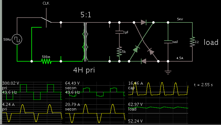
If we have a cheap inverter which produces a rough 'stair-step' type mains waveform, then presumably if it used to supply equipment which comprises a mains transformer, then the mains transformer primary inductance will filter the stair-step waveform to make it smooth...(ie make the current smooth)?

However, if the equipment being supplied by the cheap inverter's output was a switch mode power supply , then there would be more problems, as this stair-step voltage supply would cause heavy repeated inrush currents into the post rectifier bridge capacitor?
 

the mains transformer primary inductance will filter the stair-step waveform to make it smooth...(ie make the current smooth)?

The inrush current per cycle that loads the capacitor after diode bridge tends to "instantly" saturate the core, featuring a certain damping effect to waveform, certainly negligible. Also, the effect of parasitic inductance transformer may not have much relevance in that case, if compared to the capacitor after the diode bridge.

The smoothing effect observed on voltage waveform has not the same proportion on current, more precisely, the surge current will be higher as the higher the perceived damping will be.
 
  • Like
Reactions: treez

    T

    Points: 2
    Helpful Answer Positive Rating
Here is a simulation. The capacitor appears to get a sine-like waveform, due to inductive smoothing effect as you suggest. (However there is surge for a few cycles on power-up.)

Since you mention 'staircase', I made the power supply a modified sine type.

Comparing voltage veruss current, the waveforms are different. The voltage has a square-ish shape, but the Ampere waveform is sine-like.

The Ampere waveform rises and falls one time, starting when the voltage waveform changes state. This happens both on the primary and secondary side.


The transformer has the default 4H primary value. But if it is reduced, then surges increase in severity at the capacitor.
 
  • Like
Reactions: treez

    T

    Points: 2
    Helpful Answer Positive Rating
Thanks to you both,
of course , it would only be the magnetising current that gets slowed up by the primary, the power current would slam through the transformer.
I think that that there is a problem with high repetitive surging inrush currents into post-bridge -capacitors where "stair-step" inverters are used.
I wonder why such cheap , "stair-step" output inverters are so common?...I mean, no smps can realistically be fed by them?
 

First remark. The transformer primary inductance has no smoothing effect. If at all, the leakage inductance (along with the windings resistance) has.

Secondly, you get relative high peak currents into a rectifier bridge with regular sine input voltage. The peak current isn't considerably increased when you supply the rectifier by a staircase (so-called "modified sine") inverter.

Means this inverter type is well suited to supply electronic appliances with rectifier input, with or without mains transformer. The inverter must be able to withstand the peak current, but it's "normal operation" for the rectifier.
 
  • Like
Reactions: treez

    T

    Points: 2
    Helpful Answer Positive Rating
I think that that there is a problem with high repetitive surging inrush currents into post-bridge -capacitors where "stair-step" inverters are used.
I wonder why such cheap , "stair-step" output inverters are so common?...I mean, no smps can realistically be fed by them?

Note that the for the standard linear power supply based only on rectification of sinusoidal waves, the whole charge transfer from transformer to capacitor occurs at an instantaneous event ( near to the peak of sinewave ) that is it is a much more stressful operation to the capacitor if compared to continuously conducting a current that ressupply the load along the charge drain performed by the SMPS ( which extracts the energy of the capacitor during a longer period of the sinewave cycle )
 
  • Like
Reactions: treez

    T

    Points: 2
    Helpful Answer Positive Rating
Secondly, you get relative high peak currents into a rectifier bridge with regular sine input voltage. The peak current isn't considerably increased when you supply the rectifier by a staircase (so-called "modified sine") inverter.

I am inclined to agree with you, because otherwise I guess cheap, modified sine wave inverters wouldn't be very popular. The thing is, I = C.dv/dt....and dv/dt is definitely much higher with a "stair-step" cheap inverter output....therefore, current will be greater, significantly so, surely?
 

The thing is, I = C.dv/dt....and dv/dt is definitely much higher with a "stair-step" cheap inverter output....therefore, current will be greater, significantly so, surely?
It isn't under realistic conditions. In constrast, power and crest factor are considerably improved.

First point is that conduction angle is increased to about 90 degree respectively 50 percent of a halfwave. So capacitor voltage drops by a smaller amount.

Secondly, even a small transformer leakage inductance eliminates the peak currents that you expect related to the theoretically high dV/dt.
 
  • Like
Reactions: treez

    T

    Points: 2
    Helpful Answer Positive Rating
Secondly, even a small transformer leakage inductance eliminates the peak currents that you expect related to the theoretically high dV/dt.

Yes agreed, but I am mainly speaking about rectifier bridge/smoothing capacitor/SMPS power stages, not mains transformer types...though yes, I am proposing that mains transformers work better with cheap stair-step inverter outputs than SMPS's.
 

O.K., you get higher peak currents without any series inductor. But the power factor is still better with square wave and capacitor RMS current respectively lower.
 
  • Like
Reactions: treez

    T

    Points: 2
    Helpful Answer Positive Rating
thanks, supposing I wished to run a 100W SMPS, with a boost power factor stage in it, would this be feasible to do from the output of a cheap, stair-step inverter output?........what I mean is, is it feasiable, -I understand that the power factor wouldn't be good.......I presume that realistically speaking, if the power of the smps is >75W, there would be no advantage whatsoever of having a PFC stage in the SMPS, when the supply is the output of a cheap stair-step inverter.?
 

Status
Not open for further replies.

Part and Inventory Search

Welcome to EDABoard.com

Sponsor

Back
Top