Continue to Site

Welcome to EDAboard.com

Welcome to our site! EDAboard.com is an international Electronics Discussion Forum focused on EDA software, circuits, schematics, books, theory, papers, asic, pld, 8051, DSP, Network, RF, Analog Design, PCB, Service Manuals... and a whole lot more! To participate you need to register. Registration is free. Click here to register now.

Square Wave through a transformer, help diagnose this waveform?

Status
Not open for further replies.

ErikG

Newbie level 4
Joined
Apr 19, 2013
Messages
7
Helped
0
Reputation
0
Reaction score
0
Trophy points
1,281
Activity points
1,346
hey all,

I am working on a project and i am having an issue i hope you can help with.
I am driving a square wave signal into a primary of a transformer and using this to inductively couple a signal into a power line, in this case the power line is only 12v. The output of a processor is used to drive a FET and this in turn switches 10v into the primary of the transformer. I have a resistor(82ohm) in series with the output of the fet for current limiting.

If you direct your attention to the scope capture below, have a look at the blue(top) trace. This is the input to the transformer, after the resistor. Is this effect caused by capacitance, or inductance in the transformer or a bit of both? is there a way that i can get a more square wave into this transformer using a LC circuit of some kind? I am inclined to believe that the shape of this signal is affecting the amount of energy getting coupled to the secondary and is causing distortion on the receive side. The square waves are carrying data modulated via FSK.

TEK00043.PNG

Thank you for you time, ill check back frequently and answer any questions.
-Erik
 

What are the other three signals that have different frequencies?
I think the first trace of the voltage feeding the transformer shows that the transformer does not have enough low frequency response. Trace #4 looks similar and also has a fairly low frequency.
 

Hi,

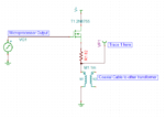
A schematic could help. Pleas show where you measured the scope signals.

Klaus
 

Here is a schematic.

Capture.PNG

@audioguru, all signals are the same frequency 10kHz, The 4th trace is the received signal at the other transformer. The middle 2 traces are the output of the filter on the receiving side. I believe the jitter seen there is caused by inefficient coupling of the signal to the transmission line. the received signal is passed into a filter and then comparator circuit(middle traces are after the gain circuit). my only concern here is that 1st trace.

@klaus, see above.

Thanks all!
-Erik
 

I believe that the transformer does not have enough inductance and does not have enough low frequency response for your frequency. You can prove it by increasing the 10kHz to 50kHz then the waveform feeding the transformer should improve with flatter top and bottom.
 

@audioguru, thanks for the input. ill go run that test right now, ill let you know what the outcome is... Ok so yeah, around 100kHz i get a much better looking signal. However the coaxial cable i am using has a bunch of attenuation at higher frequencies so i am trying to keep my frequencies low. as it now, the The inductance from the data sheet of the transformer is 1.23 mH in case that helps.

Now that we are honing in on the issues with the transformer, lets go into tuning the system for a minute if you dont mind. assuming a transformer with the correct inductance, Should i tune the circuit with capacitor in series with the primary to create an LC circuit that is resonant at 10kHz? or should that go on the secondary side? or no tuning at all?
Thanks!
-Erik
 

I don't understand part of the discussion. A FSK modem transmits frequency infomation, you don't actually care much for signal waveform. A FSK signal transmitted over a line will rather look like a sine than a square wave, at the latest when it's filtered at the receiver side.

What you really care for is received signal and impedance matching. The shown (partly differentiated) square waves shows of course that the transformer inductance matters, but it must not necessarily indicate a problem. I say must not necessarily because you didn't tell any quantitative parameters that allow to assess the transmission quality.
 

Hi

The "distorted" waveform is quite usual.

When you switch ON any inductive load, then at start the current is low and increasing with time.

Now you have a series resistor connected.Therefore at start the current is low, therefore the voltage drop across the resistor is low and the voltage across the inductor is high. The the current increases, voltage across resistor increases and voltage across inductor decreases.

The lower the resistir, the more it will be squarewave.

Klaus
 

@Klaus thanks for the information. I see now that the inductor and resisitor act as a and RL differentiator and behaves exactly as you describe. Is there a pulse shape that will get the most energy coupled into the system, how would i go about determining that?

Thanks,
-Erik
 

Status
Not open for further replies.

Part and Inventory Search

Welcome to EDABoard.com

Sponsor

Back
Top