Continue to Site

Welcome to EDAboard.com

Welcome to our site! EDAboard.com is an international Electronics Discussion Forum focused on EDA software, circuits, schematics, books, theory, papers, asic, pld, 8051, DSP, Network, RF, Analog Design, PCB, Service Manuals... and a whole lot more! To participate you need to register. Registration is free. Click here to register now.

Square wave generation with inverter chain

Status
Not open for further replies.

parkpika

Junior Member level 3
Joined
Jun 18, 2013
Messages
26
Helped
0
Reputation
0
Reaction score
0
Trophy points
1
Location
parkpika
Activity points
183
I've heard that you can generate a square wave from a sine wave using an inverter chain. Why does this work?

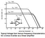
The voltage characteristic of an inverter looks more like a curve, not a step. Does cascading inverters help it look more like a step? why??

Thanks
 

Normally an inverter outputs either high or low, based on whether the input is below or above supply V/2.

Whether the input changes slowly or quickly, the output slews very quickly. Conceivably you can add a second or third inverter to obtain even faster transitions.

Perhaps you are talking about an unusual non-digital application for the 4069 IC? Three of them cascaded makes an analog amplifier (with the help of a couple of resistors). The output ranges in the middle region between high or low.

This is an analog role for a digital device. I saw this in the Forrest Mims Engineer's Notebook. The unbuffered 4069 UBE version is recommended for this purpose.
 

If the input is near V/2, it won't slew right? It will only start slewing if one of them is turned off right?
 

I suppose, you speak about the CMOS inverter?
Yes - it can be used as a linear amplifier for analog purposes (amplifier, oscillator).
For this purpose, you must bias the input at Vdd/2 using a feedback resistor between output and input.
Then, apply a sinusoidal signal through a coupling capacitor and verify the amplification property.
 

If the input is near V/2, it won't slew right? It will only start slewing if one of them is turned off right?

I guess I only know enough to address your first question.

When the input crosses V/2, the inverter changes state. It slews suddenly.

I once tested an inverter's behavior. I shifted the input voltage up and down, slowly as I could, trying to make the output change slowly. But all I could do was make the output change suddenly. And it always changed at the same level, when the input crossed V/2.

There is the schmitt trigger, which goes high when the input crosses a volt level, and it goes low when the input crosses a different level.
 

RCA invented Cmos logic ICs a long time ago. They published a graph that shows the fairly high voltage gain of unbuffered Cmos inverters. With a small input signal level then the output clips it into a squarewave. With a larger input level then the clipping is more and the squarewave is even better.

Only when the output is as high as it can go or is as low as it can go then one of the Mosfets is turned off.
 

Attachments

  • Cmos amp.PNG
    Cmos amp.PNG
    18.6 KB · Views: 104

Status
Not open for further replies.

Part and Inventory Search

Welcome to EDABoard.com

Sponsor

Back
Top