Continue to Site

Welcome to EDAboard.com

Welcome to our site! EDAboard.com is an international Electronics Discussion Forum focused on EDA software, circuits, schematics, books, theory, papers, asic, pld, 8051, DSP, Network, RF, Analog Design, PCB, Service Manuals... and a whole lot more! To participate you need to register. Registration is free. Click here to register now.

Spiral inductors Simulation and Measurements examples

Status
Not open for further replies.

matte87

Member level 1
Joined
Mar 9, 2011
Messages
34
Helped
4
Reputation
8
Reaction score
4
Trophy points
1,288
Activity points
1,553
Hi,
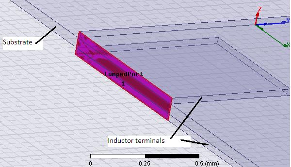
i'm trying simulate some spiral inductors and I would like to compare my results with some existent inductor in order to verify my simulations and my model.

I tried to look out on the web but i didn't find anything useful.

Do you have any suggestions?

Thanks in advance,
Mat
 

Hi matte87,
You can simulate spiral inductors in Ansoft HFSS. kindly refer the link https://www.edaboard.com/threads/203359/ especially the tutorial provided by sweetchoto.
Hope this helps...

Hi Vinoth,
thank you for your reply.
Actually I'm already using HFSS, and the raison why I need some example is to validate my hfss simulations. I'm finding some strange results (in particular the resonant frequency of the coil) and I think that there is something wrong with my design...I posted some months ago about this problem (you can find here https://www.edaboard.com/threads/205177/) but as you can see nobody answered me ( :-? ). I solved the problem with the resistance solving inside the conductor, but as the frequency goes up my results get strange...If you can help me it would be very appreciated...


thank you very much,
Matte
 

**broken link removed**
 
Hi Vfone,
thank you for your reply.
I read the file and now I have some doubts on how assign the lumped port. At page 53 he says : "to include the effect....we usually want to simulate as a 2 port so that...." so he suggest to set up a 2 port simulation instead of a single lumped port for one inductor..why? In my case, the substrate losses can be neglected (FR4)..In my simulation I used one lumped port connected to the conductor terminals.
So it looks like:


Is it correct?
Thank you very much,
matte
 

Theoretically is better to use differential ports, as was stated, because both ports will have the same ground reference.
Using one lumped port shouldn't give you very different results than using differential ports, but have to check your simulation settings.
 
Hi,
I tried with both types of ports, single and differential ports, but the results are almost the same. I found an interesting example in this paper ( **broken link removed** ) where there are model results, measurements and simulation, so a good way to validate my model and simul. The problem is that i get a resonant frequency at 28 MHz instead of 53 MHz, I tried to do different types of simulation but nothing changes...can you suggest me something? thank you very much..
 

Status
Not open for further replies.

Similar threads

Part and Inventory Search

Welcome to EDABoard.com

Sponsor

Back
Top