Continue to Site

Welcome to EDAboard.com

Welcome to our site! EDAboard.com is an international Electronics Discussion Forum focused on EDA software, circuits, schematics, books, theory, papers, asic, pld, 8051, DSP, Network, RF, Analog Design, PCB, Service Manuals... and a whole lot more! To participate you need to register. Registration is free. Click here to register now.

Spice correlation issue

Status
Not open for further replies.

_suraj

Newbie
Joined
Jan 15, 2021
Messages
3
Helped
0
Reputation
0
Reaction score
0
Trophy points
1
Activity points
78
Hello,

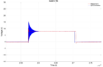
I am simulating LT8641 (step-down dc-dc converter) on LTspice. I have a PCB fabricated with the same IC as well. I am looking to correlate the functionalities of the PCB with measurements and simulations. I have used a netlist with the PCB parasitics for simulations but I am not able to match the risetime and falltime of the measurement results. Any suggestions on what parameters need to be tweakedfor a better correlation?
 

Do you believe the models for the chip and its
internal FETs? Those can be "optimistic".

Your 'scope probe's contribution to capacitance
of the measured node, should dwarf PCB trace
parasitics other than very fat traces over
adjacent-layer ground plane. You might like to
try putting a 100ohm to 1Kohm resistor in series
with the probe tip, although this will limit the
risetime to ~ 1/RseriesCprobe (1nS - 10nS). It may
not change the ultimate measurement BW in
a positive way but it can get rid of significant
ground loop impulse artifacts.

Check that your 'scope channel is not set with
vertical BW limit at the 20MHz corner setting....
 

For the measurements, I'm using a 1GHz-BW, 5Gs/s-Sampling rate scope, and a 3GHz -BW, 0.6pF i/p capacitor active probe.
The table and the image is a comparison of the rise time, fall time, and ringing frequency between measurements and LTspice simulation.
The rise time, fall time of the simulation is sharp when compared with the measurements.
Similarly, the ringing freq of the simulations has a significant error rate.
Can this question the validity of the IC-model??

PS: I'm okay with an error rate of (10-15)% for the measurement and sim correlation.


Input VoltageRload (IA)Switching Frequency (Rfsw)Rise Time FallTimeRinging Freq
MEASIMMEASIMMEASIM
8V5Ω (1A)93.5KΩ (466KHz)1.1ns0.256ns3.26ns0.157ns~260MHz666MHz
 

Attachments

  • Picture 1.png
    Picture 1.png
    121.2 KB · Views: 94

I expect your ringing is mostly external to the
IC. Most likely the SRF of decoupling caps in the
context of their local layout, but also any distance
between probe ground point and signal (a loop
to pick up edge EMI).

I'd expect if you put a few nH in the circuit between
decoupling cap and IC, decoupling cap and ground
and some between IC ground and ground plane
(as realistic as you can manage) your simulated
ring-note would shift down toward bench readings.
So too, any info you can find on capacitor(s) ESL
and ESR, if you care about this stuff then each cap
wants a valid subcircuit model plus some top
level expression of its access R, L, C.
 

Is it advisable to use a few nH of inductance between the decoupling cap and IC even while using a subcircuit model??

Also, what are your thoughts about improving the rise and fall times of the simulations w.r.tthe measurements??
 

Status
Not open for further replies.

Part and Inventory Search

Welcome to EDABoard.com

Sponsor

Back
Top