Continue to Site

Welcome to EDAboard.com

Welcome to our site! EDAboard.com is an international Electronics Discussion Forum focused on EDA software, circuits, schematics, books, theory, papers, asic, pld, 8051, DSP, Network, RF, Analog Design, PCB, Service Manuals... and a whole lot more! To participate you need to register. Registration is free. Click here to register now.

SPI Level Shifter

Status
Not open for further replies.

emaq

Member level 4
Joined
Sep 17, 2015
Messages
78
Helped
0
Reputation
0
Reaction score
1
Trophy points
1,288
Activity points
2,001
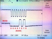
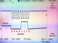
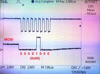
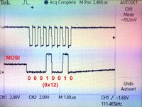
I need to connect a 5V sensor to Raspberry Pi 3.3V SPI using a conventional level translator on all 4 SPI lines (MOSI, MISO, SCLK and ~CS) but it does not seem to work. The schematic of the level shifter is as under.

level_shifter.png


I have tested the same 5V sensor on Arduino Uno SPI and it works fine.

Are the 10k pull-up resistors a problem? If so what other options do I have?
 

Hi,

Your circuit usually is for "bidirectional open collector" signals like I2C SDA.
But SPI is "unidirectional push pull".

There are dedicated level shifters.
3.3V --> 5V: any 5V supplied HCT logic gate will do
5V --> 3.3V: a 3.3V supplied AHC1G125 is good

There are several discussions here in the forum...

Klaus
 

But SPI is "unidirectional push pull".
Is it possible to directly connecting Raspberry Pi MOSI, SCLK, and CS and, 5V to 3.3V voltage divider on MISO??

Would the Raspberry Pi 3 MOSI, SCLK, and CS pins tolerate 5V? I know they are driving and not driven by 5V, but still tolerable and works?
 

Hi,

Sorry, you did not say which "sensor" you use, thus we can't know it's V_IH specification.
You have the sensor name, so you can look into it's datasheet.

The same is RPi.
Either you or one of us have to look whether RPi input is 5V tolerant. (better you do)

But MISO at slave should be tri-state ... it must be tri-state when there are more than one slaves on the bus. We don't know.

Klaus
 

Would the Raspberry Pi 3 MOSI, SCLK, and CS pins tolerate 5V? I know they are driving and not driven by 5V, but still tolerable and work?
Makes no sense. The signals are driven by push-outputs, the level is determined by Raspery Pi supply voltage.

Problem of the level translators in post #1 is slow operation with 10k pull-ups. They might work with lower resistor values, however CMOS buffers as suggested in post #2 are preferred.
 

Hi,

Sorry, you did not say which "sensor" you use, thus we can't know it's V_IH specification.
You have the sensor name, so you can look into it's datasheet.
Please have a look at the following link of the datasheet of the sensor and suggest if there will be an issue directly connecting 3.3V master side MOSI, SCLK, and CS to the sensor? I think the V_IH specification is on page 4.
https://www.analog.com/media/en/technic ... S16354.pdf
 

Hi,

why don´t you try it on your own? Sooner or later you should learn to read datasheets.
You correctly recognized page 4.

Klaus
 

Hi,

why don´t you try it on your own? Sooner or later you should learn to read datasheets.
You correctly recognized page 4.
Just wanted a confirmation! Would it work?
I don't want to damage my Pi board at this point!
 
Last edited:

Klaus

There is a following foot note on page 4 for LOGIC INPUTS and DIGITAL OUTPUTS, which I don't understand.

The digital I/O signals are driven by an internal 3.3 V supply and the inputs are 5 V tolerant.
 

Hi,

"are driven" means "as outputs", so when configured as output, the output voltage is nominally 0V/ 3.3V. But when loaded (load current) the voltages will vary. Usually there is a chart that shows voltage vs current.

But when configured as inputs you may put up to 5V to the input, even when the supply voltage is 3.3V only.

Klaus
Does this imply that I can safely connect the sensor with 5V supply to Raspberry Pi 3.3V SPI directly without any level shifter?
 

Last edited by a moderator:

-CS doesn't seem to be an issue but we need to see the relationship between the clock and data line edges to see if it is being latched properly.
Your DIN=>MOSI looks suspicious, the level shifter would never allow a floating (half supply) condition because it has pull-up resistors at both sides. Is it possible you are driving a line you should be receiving on and causing a 'collision' of drive signals?

Brian.


It's unusual to tristate MOSI between SPI transactions, but this must not necessarily be a problem.

To understand, if the device should respond to the command, we would need to know the sent data. To check the SPI timing for correct mode, at least SCK and MOSI should be shown together in a waveform. According to datasheet, ADIS16354 is expecting 16-bit data frames, but you are sending 8-bit data frames, so it's unlikely that the transaction has any response.
 

According to datasheet, ADIS16354 is expecting 16-bit data frames, but you are sending 8-bit data frames, so it's unlikely that the transaction has any response.

I have modified several Analog Devices IMU drivers for PX4 project to run in 8-bit SPI mode instead of 16-bit, since the Raspberry Pi does not support 16-bit SPI transfer under Linux.

Interestingly the IMU sensor works fine with Arduino Uno SPI with a similar 8-bit transfer mode (see the following code). However, the same 5V sensors (ADIS16362 and ADIS16354) are not working with Raspberry Pi SPI. I have used a similar driver with 8-bit SPI mode for ADIS16477 which is a 3.3V sensor and it worked fine with Raspberry Pi SPI.

I will post the SCK and MOSI waveform soon.

Code:
/*
  Arduino UNO and ADIS16354

  pin 10               CS -     SS
  pin 11               DIN -    MOSI
  pin 12               DOUT -   MISO
  pin 13               SCK -    SCLK
*/

#include <SPI.h>

#define SUPPLY_OUT  0X02
#define XGYRO_OUT   0X04
#define YGYRO_OUT   0X06
#define ZGYRO_OUT   0X08
#define XACCL_OUT   0X0A
#define YACCL_OUT   0X0C
#define ZACCL_OUT   0X0E
#define XTEMP_OUT   0X10
#define YTEMP_OUT   0X12
#define ZTEMP_OUT   0X14
#define AUX_ADC     0X16

#define XGYRO_OFF   0X1A
#define YGYRO_OFF   0X1C
#define ZGYRO_OFF   0X1E
#define XACCL_OFF   0X20
#define YACCL_OFF   0X22
#define ZACCL_OFF   0X24
#define ALM_MAG1    0X26
#define ALM_MAG2    0X28
#define ALM_SMPL1   0X2A
#define ALM_SMPL2   0X2C
#define ALM_CTRL    0X2E
#define AUX_DAC     0X30

#define GPIO_CTRL   0X32
#define MSC_CTRL    0X34
#define SMPL_PRD    0X36    // TS = TB × (NS + 1)

#define SENS_AVG    0X38
#define SLP_CNT     0X3A
#define STATUS      0X3C
#define COMMAND     0X3E

static constexpr uint16_t DIR_WRITE = 0x80;
int incomingByte = 0;
int ss = 10;

void setup() {
  Serial.begin (9600);
  pinMode(ss, LOW);
  SPI.begin();
  SPI.beginTransaction(SPISettings(2000000, MSBFIRST, SPI_MODE3));
}

// convert 12 bit integer format to int16.
static int16_t convert12BitToINT16(uint16_t word) {
  int16_t output = 0;

  if ((word >> 11) & 0x1) {
    // sign extend
    output = (word & 0xFFF) | 0xF000;

  } else {
    output = (word & 0x0FFF);
  }

  return output;
}

// convert 14 bit integer format to int16.
static int16_t convert14BitToINT16(uint16_t word) {
  int16_t output = 0;

  if ((word >> 13) & 0x1) {
    // sign extend
    output = (word & 0x3FFF) | 0xC000;

  } else {
    output = (word & 0x3FFF);
  }

  return output;
}

static constexpr int16_t combine(uint8_t msb, uint8_t lsb) {
  return (msb << 8u) | lsb;
}

void RegisterWrite(uint16_t reg, uint16_t value) {
  uint8_t cmd[4] {};
  cmd[0] = (((static_cast<uint16_t>(reg)) & 0x00FF) | DIR_WRITE);
  cmd[1] = (0x00FF & value);
  cmd[2] = (((static_cast<uint16_t>(reg) + 1) & 0x00FF) | DIR_WRITE);
  cmd[3] = ((0xFF00 & value) >> 8);

  digitalWrite(ss, LOW);
  SPI.transfer(cmd[0]);
  delayMicroseconds(9);
  digitalWrite(ss, HIGH);;

  digitalWrite(ss, LOW);
  SPI.transfer(cmd[1]);
  delayMicroseconds(9);
  digitalWrite(ss, HIGH);

  digitalWrite(ss, LOW);
  SPI.transfer(cmd[2]);
  delayMicroseconds(9);
  digitalWrite(ss, HIGH);

  digitalWrite(ss, LOW);
  SPI.transfer(cmd[3]);
  delayMicroseconds(9);
  digitalWrite(ss, HIGH);
}

uint16_t RegisterRead(uint16_t reg) {
  uint8_t cmd[2] {};
  cmd[0] = ((static_cast<uint16_t>(reg)) & 0x00FF);
  cmd[1] = 0x00;

  digitalWrite(ss, LOW);
  SPI.transfer(cmd[0]);
  delayMicroseconds(9);
  digitalWrite(ss, HIGH);

  digitalWrite(ss, LOW);
  SPI.transfer(cmd[1]);
  delayMicroseconds(9);
  digitalWrite(ss, HIGH);

  digitalWrite(ss, LOW);
  cmd[0] = SPI.transfer(reg);
  delayMicroseconds(9);
  digitalWrite(ss, HIGH);

  digitalWrite(ss, LOW);
  cmd[1] = SPI.transfer(reg);
  delayMicroseconds(9);
  digitalWrite(ss, HIGH);

  int16_t reg_data = combine(cmd[0], cmd[1]);
  return reg_data;
}

void loop() {
  // Read gyro/accel output registers directly (14-bit data)
  int16_t xgyro = RegisterRead(XGYRO_OUT);
  int16_t ygyro = RegisterRead(YGYRO_OUT);
  int16_t zgyro = RegisterRead(ZGYRO_OUT);
  int16_t xaccel = RegisterRead(XACCL_OUT);
  int16_t yaccel = RegisterRead(YACCL_OUT);
  int16_t zaccel = RegisterRead(ZACCL_OUT);
  // gyro temperature measurement (12-bit data)
  uint16_t temp_x = RegisterRead(XTEMP_OUT);
  uint16_t temp_y = RegisterRead(YTEMP_OUT);
  uint16_t temp_z = RegisterRead(ZTEMP_OUT);

  // convert 14-bit data to 16-bit
  int16_t gyro_x = convert14BitToINT16(xgyro);
  int16_t gyro_y = convert14BitToINT16(ygyro);
  int16_t gyro_z = convert14BitToINT16(zgyro);
  int16_t accel_x = convert14BitToINT16(xaccel);
  int16_t accel_y = convert14BitToINT16(yaccel);
  int16_t accel_z = convert14BitToINT16(zaccel);
  // convert 12-bit data to 16-bit and set temperature scale (0.145 °C/LSB, 25 °C = 0x000)
  const float x_gyro_temperature = (convert12BitToINT16(temp_x)) * 0.1453f;
  const float y_gyro_temperature = (convert12BitToINT16(temp_y)) * 0.1453f;
  const float z_gyro_temperature = (convert12BitToINT16(temp_z)) * 0.1453f;
  const float temperature = (x_gyro_temperature + y_gyro_temperature + z_gyro_temperature) / 3.f;

  // sensor's frame is +x forward, +y left, +z up
  // flip y & z to publish right handed with z down (x forward, y right, z down)
  accel_y = (accel_y == INT16_MIN) ? INT16_MAX : -accel_y;
  accel_z = (accel_z == INT16_MIN) ? INT16_MAX : -accel_z;
  gyro_y = (gyro_y == INT16_MIN) ? INT16_MAX : -gyro_y;
  gyro_z = (gyro_z == INT16_MIN) ? INT16_MAX : -gyro_z;

  //  Serial.print("Gyro x: 0x");
  //  char buf1[9];
  //  sprintf(buf1, "%04x", gyro_x);
  //  Serial.println(buf1);

//  /*
    // Gyro data
    Serial.print("gyro_x");
    Serial.print(",");
    Serial.print(gyro_x);
    Serial.print(" ");
    Serial.print("gyro_y");
    Serial.print(",");
    Serial.print(gyro_y);
    Serial.print(" ");
    Serial.print("gyro_z");
    Serial.print(",");
    Serial.print(gyro_z);
    Serial.print(",3500,-3500");
    Serial.println();
//  */

  /*
    // Accel data
    Serial.print("accel_x");
    Serial.print(",");
    Serial.print(accel_x);
    Serial.print(" ");
    Serial.print("accel_y");
    Serial.print(",");
    Serial.print(accel_y);
    Serial.print(" ");
    Serial.print("accel_z");
    Serial.print(",");
    Serial.print(accel_z);
    Serial.print(",3000,-1500");
    Serial.println();
  */

  /*
    // Temp data
    Serial.print("Temp");
    Serial.print(" ");
    Serial.print(temperature);
    Serial.print(" ");
    Serial.print(",50,10");
    Serial.println();
  */
}
 

It's not a problem of 8 or 16-bit mode. But the sensor expects 16 clocks and 16 bits of data while CS is low. Respectively two byte transfers have to be performed.
 

To understand, if the device should respond to the command, we would need to know the sent data. To check the SPI timing for correct mode, at least SCK and MOSI should be shown together in a waveform.
 

Attachments

  • MOSI_0x0A.JPG
    MOSI_0x0A.JPG
    3.3 MB · Views: 256
  • MOSI_0x0E.JPG
    MOSI_0x0E.JPG
    3.1 MB · Views: 252
  • MOSI_0x08.JPG
    MOSI_0x08.JPG
    3.8 MB · Views: 265
  • MOSI_0x12.JPG
    MOSI_0x12.JPG
    3.1 MB · Views: 266

Status
Not open for further replies.

Similar threads

Part and Inventory Search

Welcome to EDABoard.com

Sponsor

Back
Top