Continue to Site

Welcome to EDAboard.com

Welcome to our site! EDAboard.com is an international Electronics Discussion Forum focused on EDA software, circuits, schematics, books, theory, papers, asic, pld, 8051, DSP, Network, RF, Analog Design, PCB, Service Manuals... and a whole lot more! To participate you need to register. Registration is free. Click here to register now.

SPI/I2C/PWM or Serial Programmable Current Source upto 500mA in resolution of 1mA

Status
Not open for further replies.

swapnil14327

Newbie level 5
Joined
Nov 1, 2013
Messages
9
Helped
0
Reputation
0
Reaction score
0
Trophy points
1
Activity points
77
Hello All,


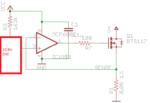
Can someone point me to a circuit, where I can pro-grammatically using SPI/I2C/PWM etc protocols set current source from 0mA to 500mA in steps of 1mA.

may be an IC or even transistor-MOSFET based circuit design.

Vin MAX= 24V Vin MIN = 3V
Vout Max= 24V

Iout= 0mA to 500mA in steps of 1mA ..

current managed completely using microcontroller and not external resistor.


Thanks in Advance..
 

Hi,

current managed completely using microcontroller and not external resistor.

I can´t think of a current source without resistor.

Can you draw a picture of your desired circuit?
I´d use a DAC (I2C, SPI) to generate an adjustable voltage. Then i´d use an OPAMP and some resistors and a FET to generate a current source.

Klaus
 

Hi,


I can´t think of a current source without resistor.

Can you draw a picture of your desired circuit?
I´d use a DAC (I2C, SPI) to generate an adjustable voltage. Then i´d use an OPAMP and some resistors and a FET to generate a current source.

Klaus

current.jpg

Hi KlausST.
Thanks for the reply..
I have attached the image.
I either want to go through A or B as per the design..
 

Hi,

I´d use B).
(To be correct this is a current sink, but you can also similarely build a curent source)

You can use almost any voltage output DAC with at least 9 bits resolution. 9 bits because of your 1mA/500mA resolution. I´d go for a 10 bit DAC.
Then a voltage divider to generate the same voltage as the shunt. (here 0.5V for a 1Ohms with 500mA)

In the feedbalck of the OPAMP you can build a R-C-R combination to improve stbility.
A comparator at the OPAMP output can show a "output OK" LED.

Klaus
Thanks for the reply Klaus..
I am suppose to make a Bill of material of this circuit..which I am not that good(not done it before)
Can you please suggest me with part numbers of 10Bit DAC and OPAMP and MOSFET..

you said, Comparator at output? I have added the MOSFET at output? can you please explain..?

I also have to check the design on actual hardware, so asking for component part numbers..

Thanks again..
 

Hi,

SMD or THM components?


***
The comparator can drive a LED just to indicate if the output current (regulation) is OK.

Klaus
 
Hi,

SMD or THM components?


***
The comparator can drive a LED just to indicate if the output current (regulation) is OK.

Klaus

SMD components will be great..if not possible Through Hole will also do..
 

Hi,

please go to your preferred distributor´s site.
Look for "DAC, 10bit". You will find a lot different types.
Then look for the preferred interface. I´d recommend an internal reference. Pincount should be <10 for simple connections.
Also check
* supply voltage,
* supply curren(if of interest),
* output should be "voltage" type
* data update rate
* linearity/precision/accuracy
...
availability
price

a lot of parameters that only you know.
***
The OPAMPshould have:
* common mode input voltage range: including ground
* output voltage low: Rail
* unity gain stable

Klaus

Hi Klaus,
Please can you confirm if the below design is suitable for my purpose,
Current Source.png

to 0mA to 500mA in resulation of 1mA.
I tried to simulate it in Proteus.
but the software was crashing..was not sure if it was the software problem or the circuit problem.
 

Attachments

  • Current Source.png
    Current Source.png
    6 KB · Views: 195

Hi,

There are values missing:
What Vcc voltage, What DAC output voltage?

The Opamp seems to be OK.
The FET is considered to be a switch. Although there is a statement, that linear drive is possible, I tend to use a simple FET.
Consider a heatsink for 12W dissipated power.

Klaus
 
Hello,
Noted of heat sink,

Will be trying the same circuit on hardware today,
The DAC was not available to me in local market, so will give input from powersupply

using UA741 as OP_AMP
PSMN004-60B as MOSFET.

Connections on OP_AMP
IN+ will start from 1V and slowly increasing.
VCC+ (in datasheet 5-40V) -> will start from 5V and slowly increasing, as and if necessary.
Vcc- -> GND

as per my observation everything should work and only increasing and decreasing the IN+ voltage should increase and decrease the current at AM-Meter.

Will update the results soon..

Thanks..

new.jpg
 

Hi,

Now you changed every device.
Oh no, I recognised the 100 Ohms is still the same.

The 741 is no rail to rail Opamp. It won't bring satisfying results.
The 2.5 Ohms will dissipate a lot of heat.
Starting with 1V input voltage means you start at 400mA wich is almost full scale.
Increasing supply voltage will not influence stability or other result, it just generates more heat in the FET.
The FET threshold voltage is too high, it won't give any meaningful results.

==> don't waste your time with these devices. Wait until you have the ones you really want to use.

Btw: I recommend to use a 100k:10k voltage divider and a 1uF in parallel to the 10k at your Opamp +input

Klaus
 
I recommend you to use BJT transistors since their low threshold voltages and their linearity. There are a lot of low-medium power transistors available and they are very cheap, even a TO-92 could handle that current if the load is not so high, if it does then a TO-220 packaged one will do.

There are several SPI and I2C DAC ICs which may reach both rails. What's your power supply voltage? You can make your own DAC (not that accurate as you are working at 10 bits) out of R-2R ladder or a very well filtered PWM (most MCUs have upto 16 bit PWM using timers).

The sense resistor should be below 1 ohm in order to improve efficiency and power loss over it.
 
Hi,

A bjt generates current errors, so a FET is the better solution.

The sense resistor value does not influence overall power dissipation.

Klaus
 
The sense resistor value does not influence overall power dissipation.
Yes, but only in the special case that the supply voltage is already fixed. It still affects output voltage range.

There's still an issue with the setup in post #12. It can't work with 741 and single supply. You either need an OP with input common mode range including ground (e.g. LM358), or a negative supply.

And you shouldn't use a huge 75A MOSFET like PSMN004-60B because it's gate capacitance can bring up stability problems.
 

Status
Not open for further replies.

Similar threads

Part and Inventory Search

Welcome to EDABoard.com

Sponsor

Back
Top